Antenna with compact LRU array

a technology of compact array and antenna, applied in the direction of individually energised antenna array, instruments, using reradiation, etc., can solve the problems of early failure or increased maintenance need, reflector-type antennas are subject to some disadvantages, and reflector antennas are less satisfactory

Active Publication Date: 2008-07-17
LOCKHEED MARTIN CORP
View PDF6 Cites 25 Cited by
  • Summary
  • Abstract
  • Description
  • Claims
  • Application Information

AI Technical Summary

Benefits of technology

[0010]An array antenna according to another aspect of the invention comprises a first cold plate defining first and second broad sides. The first cold plate is generally planar and extends in first and second dimensions. A second cold plate defines first and second broad sides, and is generally planar and extends in the first and second dimensions. The first broad side of the second cold plate lies generally parallel with the second broad side of the first cold plate and spaced therefrom to define a generally planar first volume. A plurality of cold plate wall pairs is provided. Each of the wall pairs includes first and second walls, with each of the walls of each of the wall pairs being generally planar and extending in the first dimension and in a third dimension, orthogonal to the first and second directions. The first and second walls of each of the wall pairs may be spaced apart to thereby define at least one generally planar second volume extending generally in the first and third dimensions. An edge of each of the first and second walls is affixed to the second broad side of the second cold plate at spaced-apart locations, to thereby define a plurality of third volumes lying between mutually adjacent walls of adjacent ones of the wall pairs. Each of the third volumes is generally three-dimensional, with the largest dimension of each of the third volumes extending parallel with the first dimension, and with each of the third volumes extending in the third dimension by the same distance from the second broad side of the second cold plate. The array antenna further includes a generally planar array of antenna elements supported on the first broad side of the first cold plate, and in thermal communication therewith. A controllable transmit/receive arrangement is physically juxtaposed with the second side of the second cold plate within each of the third volumes. The transmit/receive arrangement is in thermal communication with the second side of the second cold plate. A beamformer arrangement is physically located in the first volume, and electrically connected through the first cold plate with the array of antenna elements and through the second cold plate with the transmit/receive arrangement, for transmitting and receiving electromagnetic signals by way of the antenna elements and the controllable transmit/receive arrangement. In one embodiment, a control or processor module is located in each of the second volumes, and communicates with the transmit/receive arrangement, for controlling the transmission and reception of the electromagnetic signals. The control module is in thermal communication with the first and second walls of the wall pair defining its associated second volume. In a particular embodiment of this aspect of the invention, each transmit/receive arrangement has an extent in the third dimension smaller than the distance, so that a portion of the third volume is not filled by the transmit/receive arrangement, and the array antenna further comprises at least a power supply for the transmit/receive arrangement located in the portion of the third volume. In an alternative embodiment, each transmit/receive arrangement has an extent in the third dimension smaller than the distance, so that a portion of the third volume is not filled by the transmit/receive arrang

Problems solved by technology

Reflector-type antennas are subject to some disadvantages, especially when the antenna beam must be scanned rapidly.
In those cases requiring antenna beam agility, reflector antennas are less satisfactory, because the inertia of the antenna results in the need to apply large forces to obtain the necessary accelerations and decelerations.
In addition to being costly to operate, the physical stresses on the structure tend to lead to early failure or increased need for maintenance.
The reliability of electronic equipment tends to be degraded by operation at high temperatures.
The increase in power required to be handled by the power amplifiers of TR modules, in turn, leads to the probl

Method used


Image

  • Antenna with compact LRU array
  • Antenna with compact LRU array
  • Antenna with compact LRU array

Examples


Embodiment Construction

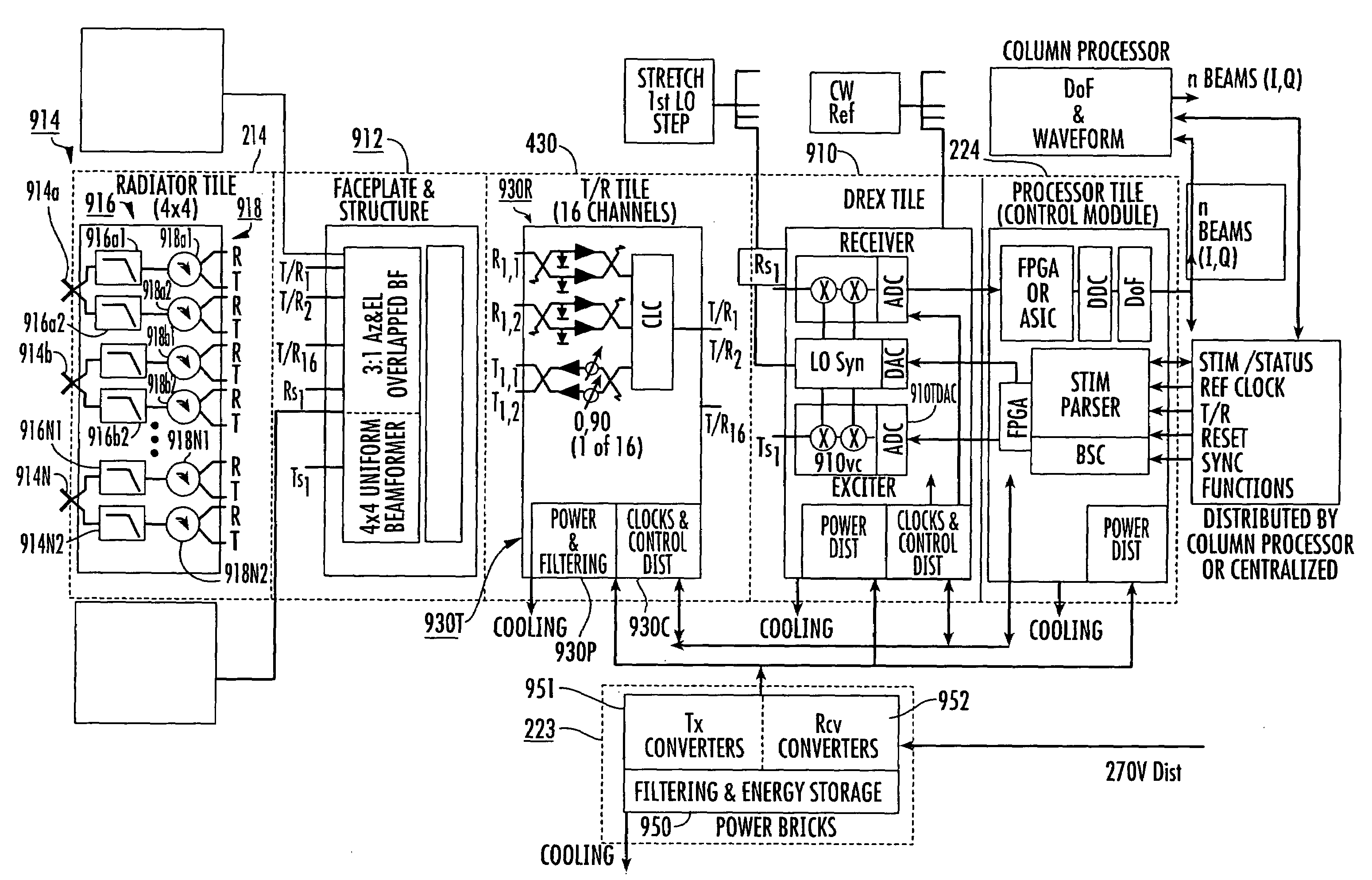
[0021]Thermal management or heat removal from the various active modules of the system is provided by transfer of the heat from the modules to the various cold plates. More particularly, it has been discovered that in high power systems, the radiating elements of the antenna array 214 of can “dissipate” (produce) significant heat, which, in conjunction with the heat produced by the transmit-receive elements, may be more than can be conveniently carried away by a single cold plate. For this reason, a set of two mutually parallel cold plates is used, one to sink heat from the radiating elements, and one to sink heat from the TR modules and the remaining LRUs. The beamformer does not generally produce a great deal of heat, but is placed between the two planar cold plates due for convenience and electrical requirements.

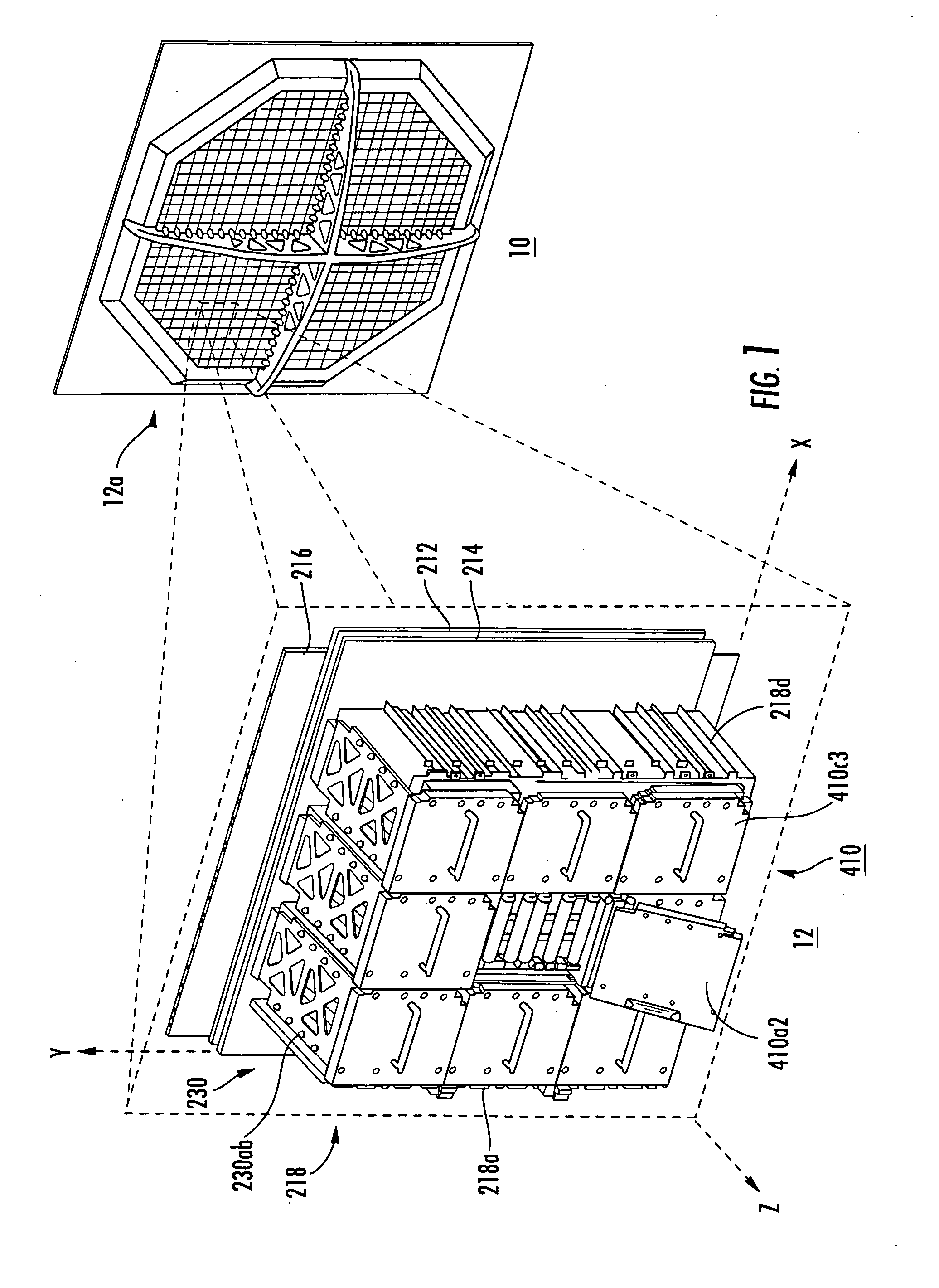
[0022]FIG. 1 is a simplified perspective or isometric view of the rear of an octagonal array antenna 10 illustrating an array 12a of antenna electronic element support st...


PUM


Abstract

An element support and thermal control arrangement for an active array antenna, preferably modular, using line-replaceable units (LRUs), includes a radiating-side liquid-cooled cold plate lying parallel with a liquid-cooled TR coldplate. Antenna elements are supported and cooled by the radiating cold plate, and a beamformer lies between the radiating and TR coldplates. A plurality of column coldplates are attached to the rear of the TR coldplate and define bays or volumes in which power LRUs can be fitted in thermal communication with the TR coldplate, the column coldplates, or both.

Description

FIELD OF THE INVENTION[0001]This invention relates to a packaging arrangement for the various elements of an array antenna, especially an active array antenna.BACKGROUND OF THE INVENTION[0002]A great deal of commerce is currently aided by the use of electromagnetic communication, and electromagnetics are widely used for sensing, as for example in radar systems. Such radar systems may be used for monitoring the flight path of an aircraft from the aircraft itself for weather and object monitoring, monitoring the airspace around an airport for traffic control purposes, distance and acceleration monitoring between automobiles, and for military purposes. Reflector-type antennas have been, and still are, widely used for obtaining the high gain desired for communication with distant locations, and to obtain a narrow radar antenna beam to allow objects to be located with more precision than if a broad antenna beam were used. Reflector-type antennas are subject to some disadvantages, especia...

Claims


Application Information

Patent Timeline
IPC IPC(8): G01S13/00H01Q21/08H01Q1/42H01Q3/00
CPCG01S7/032H01Q3/26H01Q1/02
Inventor PLUYMERS, BRIANANGELUCCI, MARC T.FRASCHILLA, JOHNDUCKER,, STUART R.MCGUIGAN, THOMAS E.LEWIS, ROBERT B.HEINRICH, RICHARD J.HARRIS, DANIEL W.
Owner LOCKHEED MARTIN CORP
Why Eureka
Try Eureka