Microwave sensor for measuring a dielectric property of a product

a dielectric property and microwave sensor technology, applied in the direction of material analysis using microwave means, safety devices for fibre treatment, lap-winding devices, etc., can solve the problem of systematic errors, limited mass loading of the resonator in the region of high field energy, and the sensing of the product over a relatively large dimension, so as to reduce the mass loading of the resonator in relation to the total energy stored in the resonator, improve the measurement accuracy, and improve the effect of mass loading

Inactive Publication Date: 2006-06-27
TRUETZSCHLER GMBH & CO KG
View PDF22 Cites 0 Cited by
  • Summary
  • Abstract
  • Description
  • Claims
  • Application Information

AI Technical Summary

Benefits of technology

[0013]The above aim can thus be achieved according to the invention in particular in that at least two half-waves of the electric field are formed in the resonator in one direction, the product feed being effected in at least one region of high field intensity of one of the half-waves of the electric field. By using at least two half-waves of the electric field, the invention enables the mass loading of the resonator in relation to the total energy stored in the resonator to be reduced, which enables the measuring accuracy to be improved and at high mass loading can possibly even prevent collapse of the electric field. According to the invention, the sample feed is arranged in a region of high field energy of at least one half-wave around a corresponding intensity maximum in order to achieve a high measuring sensitivity. This is a region having at least 50%, preferably at least 70%, more preferably at least 90% of the intensity in the field maximum. This delimits the invention from a higher-mode resonator such as that from EP 0 889 321 A, where the sample feed takes place into a central resonator region of very low field intensity.
[0014]Preferably, a product feed takes place into at least two resonator sections each corresponding to a respective half-wave of the electric field. This enables the product to be distributed over several half-waves of the electric field. This reduces the mass loading per half-wave and per resonator section. In particular, by increasing the number of half-waves the mass loading per resonator section can be reduced to a reasonable level. A relatively large expanse of a product in one direction can be covered by distribution onto several half-waves, wherein the extent of an individual region of high field strength can be relatively small. Instead of one large region of high field strength, several smaller regions of high field intensity are therefore provided, thereby enabling the overall size of the resonator as a whole to be reduced. The regions of high field strength are here generated inside a resonator; the use of several relatively small resonators is not necessary.
[0016]Around the intensity maximum of a half-wave of the electric field there exists a region of approximately homogeneous intensity, which enables the measuring accuracy to be improved when the product is arranged in the intensity maximum. In many cases, the product is therefore arranged in at least two maxima of the electric field corresponding to the at least two half-waves. If a balanced mean value of the measuring quantity is to be obtained for all parts of the product, then the product portions are arranged in each resonator section advantageously substantially in the respective maximum of the electric field. By selectively varying the arrangement of individual product portions from the maximum in the respective resonator sections, any desired weighting of the individual product portions can be set.
[0020]The resonator, if applicable the cavity resonator, can be filled with a solid dielectric having a dielectric constant greater than one, preferably at least two, more preferably at least five. Customary materials, especially ceramics, are known to the expert. The use of a dielectric filling enables field energy to be stored in a comparatively smaller space and therefore allows smaller forms of construction. Preferably, substantially the entire resonator is filled with dielectric, except for the space for receiving the sample. “Substantially” means apart from devices for coupling in microwaves, for guiding through the sample, and so on. The resonator can alternatively be filled substantially with air, however, which represents an especially simple and inexpensive construction.

Problems solved by technology

The mass loading of the resonator in the region of high field energy is limited, since too great a mass loading leads to falsification of the measuring signal owing to losses.
The use of several resonators, each one only for a portion of the product, is expensive and can lead to systematic errors owing to differences in the resonators and in the corresponding control and evaluating electronics.
In the case of extended, especially web-form, products, a further problem comprises the sensing of the product over a relatively large dimension, for example, across the entire width of a product web.
The enlargement of the region of high field energy, for example, by enlarging the wavelength, would lead to constructions of impractical dimensions.
The use of several relatively small resonators across the expanse of the product is likewise disadvantageous for the above-mentioned reasons.
The highly inhomogeneous fields at the open line ends are disadvantageous in terms of measurement techniques.
The construction of the sensor is therefore comparatively expensive.

Method used


Image

  • Microwave sensor for measuring a dielectric property of a product
  • Microwave sensor for measuring a dielectric property of a product
  • Microwave sensor for measuring a dielectric property of a product

Examples


Embodiment Construction

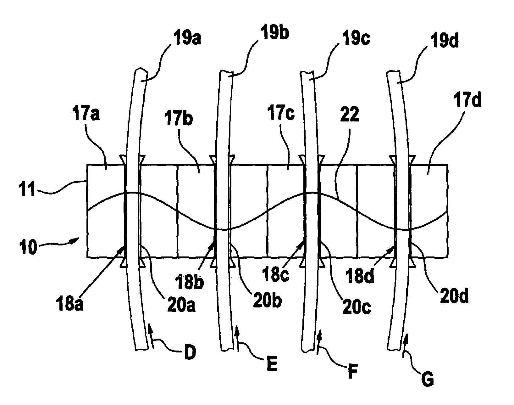
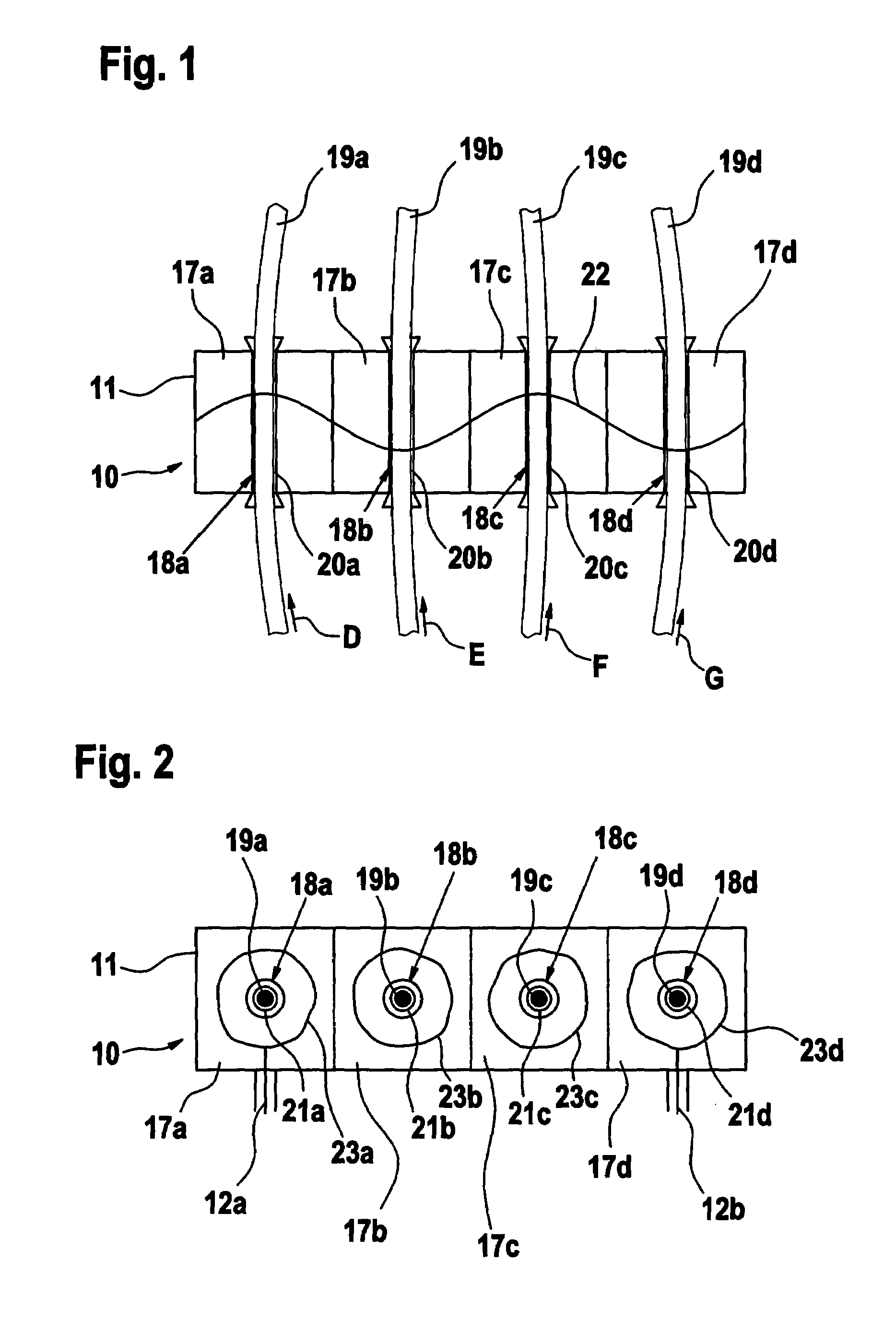
[0043]With reference to FIG. 1, a microwave sensor 10 comprises a cavity resonator 11, in which a standing microwave field is generated. The coupling and decoupling of the microwave field is effected by means of coupling devices 12. Microwaves are generated by means of a generator 14 controlled by a computer 13 and are relayed by means of a line to the coupling device 12a. A microwave signal is decoupled from the resonator 11 via the coupling device 12b and fed by means of a line to an analyser 15, the output signal of which can be processed by the computer 13. Generator 14, analyser 15 and computer 13 are expediently combined in one measuring unit 16 (cf. FIG. 8). The arrows D, E, F and G indicate the direction of flow of the material.

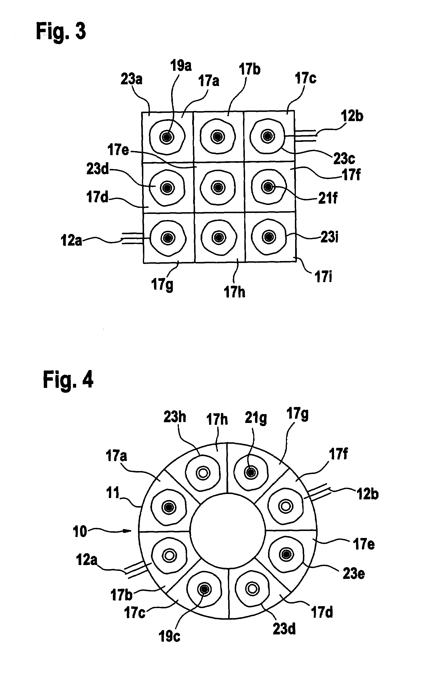
[0044]The resonator 11 has a plurality of resonator sections 17a, 17b, 17c, . . . . The division into different resonator sections is indicated in the Figures by broken lines. FIGS. 1,2, 5, 6, 7 and 9 each relate to elongate rectangular cavity resonat...


PUM

PropertyMeasurementUnit
speedaaaaaaaaaa
dielectric propertyaaaaaaaaaa
microwave fieldaaaaaaaaaa

Abstract

The application relates to a microwave sensor for measuring a dielectric property, especially the density and / or moisture content of a product, having a microwave resonator, wherein a product introduced into the resonator interacts with a resonant microwave field generated in the resonator in order to determine suitable measured quantities, and is characterized in that at least two half-waves of the electric field are formed in the resonator in one direction, the product feed being effected in at least one region of high field intensity of one of the half-waves of the electric field.

Description

CROSS REFERENCE TO RELATED APPLICATION[0001]This application claims priority from European Patent Application No. 04 003 110.6 dated Feb. 12, 2004 and from German Patent Application No. 10 2004 011 341.6 dated Mar. 5, 2004, the disclosure of each of which is incorporated herein by reference.BACKGROUND OF THE INVENTION[0002]The invention relates to a microwave sensor for measuring a dielectric property, having a microwave resonator, wherein a product introduced into the resonator interacts with a resonant microwave field generated in the resonator in order to determine suitable measured quantities related to, for example, density and / or moisture content of a product. The invention further relates to use of the sensors in a spinning preparation machine.[0003]With such sensors, the field energy is concentrated in a specific region of the resonator. The mass loading of the resonator in the region of high field energy is limited, since too great a mass loading leads to falsification of t...

Claims


Application Information

Patent Timeline
Patent Type & Authority Patents(United States)
IPC IPC(8): G01R27/04D01G31/00G01R27/26D01H13/32D06H3/10G01N22/00G01N22/02G01N22/04G01N33/36H01P1/00
CPCD01G31/006D01H13/32G01N33/362G01N22/02G01N22/04G01N22/00
Inventor PETERS, STEFFENKNOCHEL, REINHARDTAUTE, WOLFGANGDOSCHER, CLAAS
Owner TRUETZSCHLER GMBH & CO KG
Why Eureka
Try Eureka