Gas Turbine Combustor and Ignition Method of Igniting Fuel Mixture in the Same

a technology of gas turbine combustor and ignition method, which is applied in the ignition of turbine/propulsion engine, combustion type, lighting and heating apparatus, etc. it can solve the problems of large amount of no/sub>x/sub>emission, large amount of undesirable no/sub>emission, and excessive lean fuel mixture. achieve the effect of improving ignition performan

Active Publication Date: 2008-07-24
KAWASAKI HEAVY IND LTD
View PDF9 Cites 34 Cited by
  • Summary
  • Abstract
  • Description
  • Claims
  • Application Information

AI Technical Summary

Benefits of technology

[0032]The present invention improves ignition performance by forming the combustible fuel mixtu...

Problems solved by technology

A fuel mixture prepared by mixing the fuel and air by the fuel nozzle is not uniform.
A large amount of NOx emission is undesirable from the viewpoint of environmental protection and air pollution prevention.
Such a fuel mixture is excessively lean.
Under such a condition, it is possible that the low temperature of compressed air supplied to the fuel nozzle and the combustor may cause poor combustion efficiency or blow off.
Whereas uniform mixing of a large amount of air and fuel in the fuel nozzle for the lean premixed ...

Method used


Image

  • Gas Turbine Combustor and Ignition Method of Igniting Fuel Mixture in the Same
  • Gas Turbine Combustor and Ignition Method of Igniting Fuel Mixture in the Same
  • Gas Turbine Combustor and Ignition Method of Igniting Fuel Mixture in the Same

Examples


Embodiment Construction

[0066]Preferred embodiments of the present invention will be described with reference to the accompanying drawings.

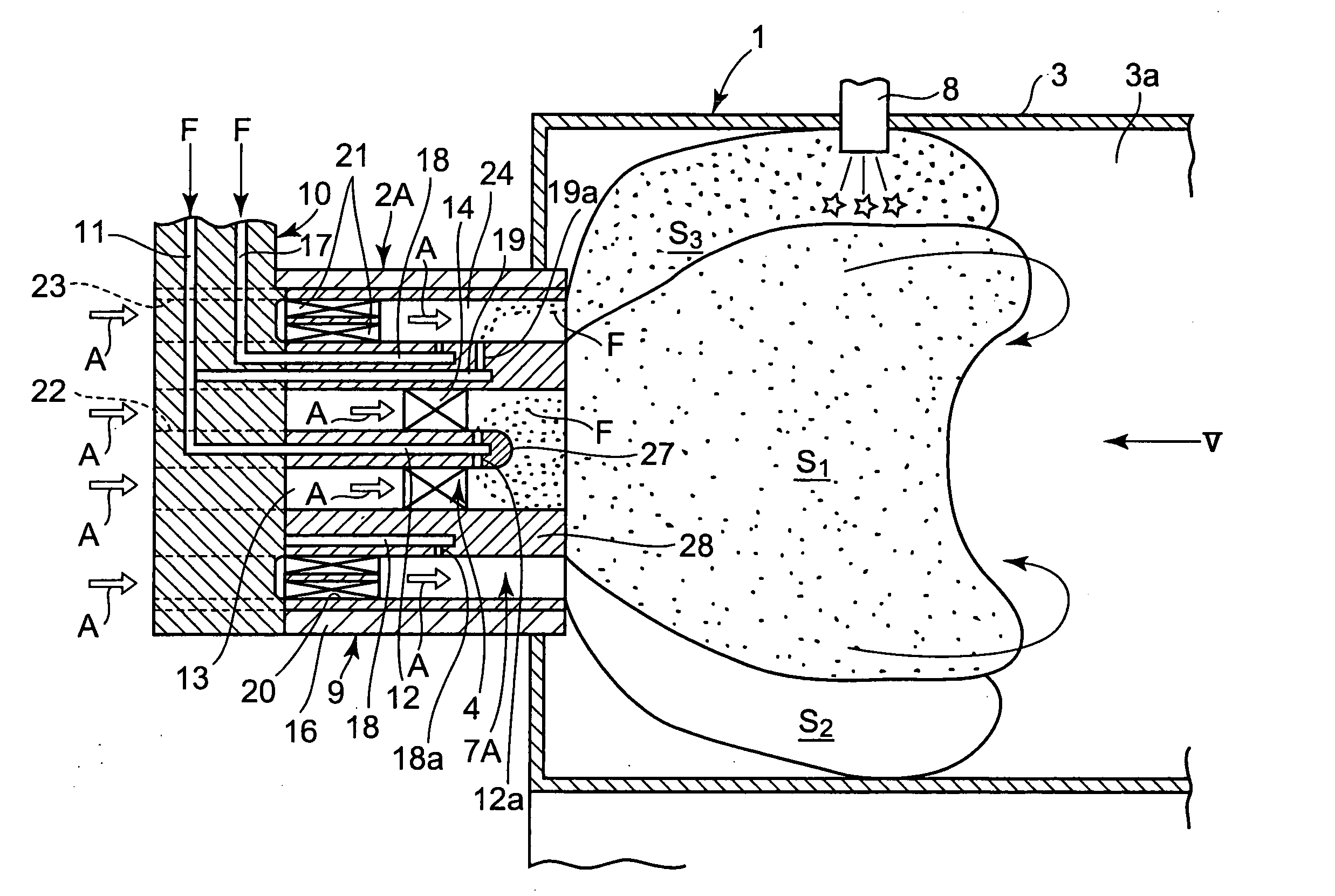
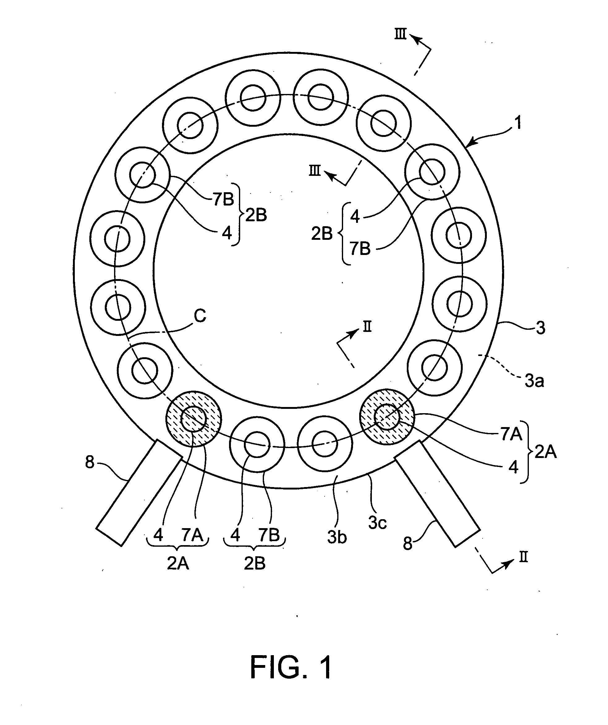
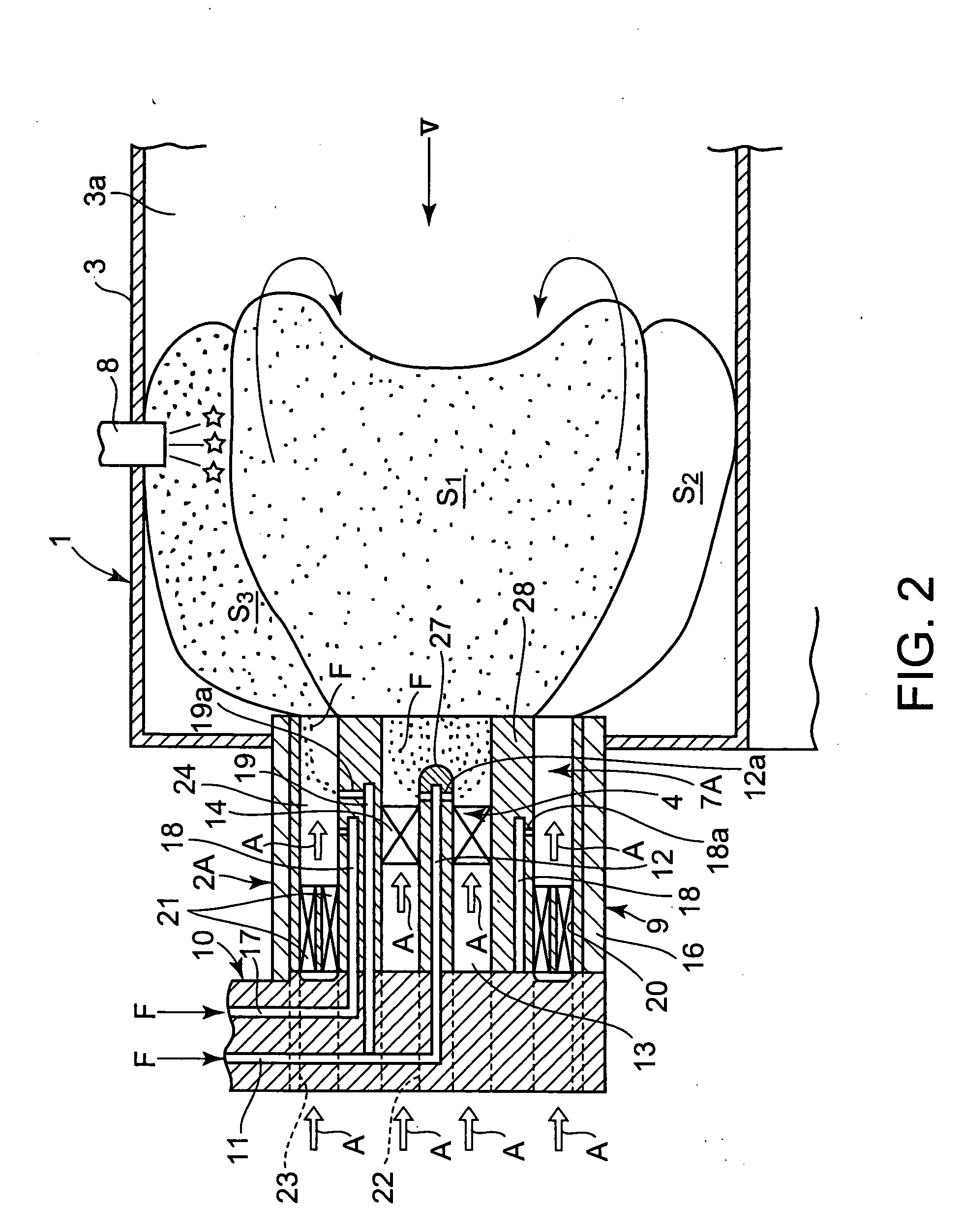
[0067]FIG. 1 shows a head unit of a gas turbine combustor 1 in a first embodiment according to the present invention. The gas turbine combustor 1 burns a fuel mixture produced by mixing fuel in compressed air supplied from a compressor included in a gas turbine, not shown, to produce a high-temperature, high-pressure combustion gas and sends the high-temperature, high-pressure combustion gas to the turbine to drive the turbine. The gas turbine combustor 1 is a combustor of the annular type provided with plural fuel nozzles 2A and 2B arranged on a circle.

[0068]The gas turbine combustor 1 is an annular combustor 3 defining a combustion chamber 3a and having an end wall 3b. The fuel nozzles 2A and 2B, namely, fuel supply devices for supplying fuel into the combustion chamber 3a, are disposed on the end wall 3b of the combustor 3 on a circle C concentric with the combustion...


PUM


Abstract

A gas turbine combustor burns a fuel mixture at a high combustion efficiency and a low NOx emission, is simple in construction and exercises improved ignition performance, and an ignition method can efficiently igniting a fuel mixture in the gas turbine combustor. A gas turbine combustor provided with fuel nozzles each having a pilot fuel injection nozzle and a main fuel injection nozzle, and fuel nozzles each having a pilot fuel injection nozzle and a main fuel injection nozzle. The fuel nozzle disposed close to an igniter is provided with a local fuel injection port through which fuel is jetted out from a predetermined position in an air passage in the main fuel injection nozzle to create a combustible fuel mixture zone in the vicinity of the igniter at least while the igniter is in an ignition operation.

Description

TECHNICAL FIELD[0001]The present invention relates to a combustor, for industrial gas turbines for aircrafts and power generation, having pilot fuel injection nozzles which delivers the fuel for diffusion combustion at least in a low-output period including an ignition period, and main fuel injection nozzles for delivering the fuel For premixed combustion only while the gas turbine combustor is in an operation in a middle- or a high-output operation mode to reduce NOx, coaxially surrounding the pilot fuel injection nozzles, and to an ignition method capable of effectively igniting a fuel mixture in the combustor.BACKGROUND ART[0002]Industrial combustors of the diffusion combustion type are used widely for driving gas turbines for aircrafts and power generators. Air flows into the conventional combustor not only through the fuel nozzle and cooling air supply openings formed in a combustor liner, but also through a dilution air supply opening formed on the downstream side of the fuel ...

Claims


Application Information

Patent Timeline
IPC IPC(8): F02C1/00
CPCF23C2201/20F23D2900/00014F23R3/343F23R3/286F23D2900/00015
Inventor KOBAYASHI, MASAYOSHININOMIYA, HIROYUKIODA, TAKEO
Owner KAWASAKI HEAVY IND LTD
Why Eureka
Try Eureka