Turbojet engine accessory gear box driveshaft; modular additional accessory

a technology of turbojet engines and accessories, applied in the direction of gearing details, machines/engines, gearing, etc., can solve the problems that the hp spool may not be able to meet the requirements of such a design satisfactorily, and achieve the effect of simplifying factory assembly

Active Publication Date: 2008-07-24
SN DETUDE & DE CONSTR DE MOTEURS DAVIATION S N E C M A
View PDF8 Cites 20 Cited by
  • Summary
  • Abstract
  • Description
  • Claims
  • Application Information

AI Technical Summary

Benefits of technology

[0006]The driveshaft structure according to the invention has the advantage of avoiding oil leaks and thus limiting fire zones. This is particularly advantageous when the structure of the intermediate casing comprises an attached outer shell ring, the number of bolted components generally increasing the risks of oil leaks.
[0009]According to another feature of the invention, the accessory comprising a drive shaft collaborates with said gear of the shaft and is designed to form a modular assembly therewith. This layout is particularly advantageous because it simplifies factory assembly of the accessory and maintenance thereof, and allows the accessory to become interchangeable. The tricky assembly and adjustment of the bevel pair can thus be performed accurately outside the turbojet engine where space is tight and generally cluttered. When it is mounted on the turbojet engine, all that remains to be done is for the various cylindrical elements of the radial transmission shaft to be plugged together. An operation such as this does not require the use of precision tooling.

Problems solved by technology

At idle speed, the HP spool may be unable satisfactorily to supply all the power required in such a design.

Method used


Image

  • Turbojet engine accessory gear box driveshaft; modular additional accessory
  • Turbojet engine accessory gear box driveshaft; modular additional accessory
  • Turbojet engine accessory gear box driveshaft; modular additional accessory

Examples


Embodiment Construction

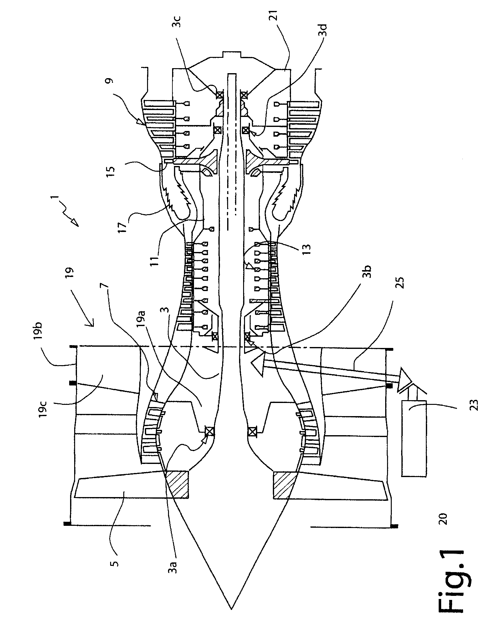
[0017]FIG. 1 schematically depicts a twin spool bypass turbojet engine with its various main components. It comprises a first shaft 3 connecting, to the left in the figure, a fan rotor 5 and the first compressor stages 7 to the low-pressure turbine 9; the assembly forms the low-pressure or LP spool. Coaxial with the first shaft, a drum-shaped second shaft 11 connects the high-pressure stages 13 of the compressor to the high-pressure turbine 15, this assembly forming the high-pressure spool HP with the combustion chamber 17. The shaft 3 is supported, at the upstream end, by the bearing 3a mounted on the casing 19 that is termed intermediate casing and, at the downstream end, by the bearing 3c mounted on the exhaust casing 21. The HP shaft here is supported by the bearing 3b of the intermediate casing 19 and at the rear by the shaft 3, via the inter-shafts bearing 3d.

[0018]The intermediate casing is made up of a hub 19asupporting the bearings 3a and 3b, of an outer shell ring 19b, pr...


PUM


Abstract

The present invention relates to an accessory gear box driveshaft (125) in a turbojet engine with intermediate casing (119), designed to be mounted in a radial arm (119c) of the intermediate casing (119), said shaft being connected, at a first end, to a means (126) of mechanical transmission to an engine shaft of the turbojet engine, and, at a second end, to a means of mechanical transmission to said box and comprising a bevel gear (125a1) between the two ends, to provide mechanical transmission to an additional accessory (128). This shaft is notable in that, together with said gear (125a1), it is contained in a case (131) forming an oil circuit sealed against said arm (119c). The invention also relates to an accessory (128) comprising a drive shaft (128a) collaborating with the gear (125a1) of the transmission shaft (125) and forming a modular assembly (130) therewith.

Description

BACKGROUND OF THE INVENTION AND DESCRIPTION OF THE Prior Art[0001]The present invention relates to the field of multispool and multiflow turbojet engines, particularly twin spool bypass turbojets. It is aimed at mounting an accessory and at the mechanical transmission between this accessory and a shaft of the engine.[0002]To drive the accessories mounted on the engine, such as electric generators, oil pumps or fuel pumps, which are necessary to the operation of the engine or that of the aircraft on which it is mounted, the required power is generally taken off the main shaft. A twin spool turbojet engine has two coaxial shafts, one of them, known as the low-pressure or LP shaft, connecting the low-pressure compressor to the low-pressure turbine and together forming the LP spool and the other, known as the high-pressure or HP shaft, connecting the high-pressure compressor to the high-pressure turbine and together forming the HP spool. In the case of such an engine, transmission of po...

Claims


Application Information

Patent Timeline
Patent Type & Authority Applications(United States)
IPC IPC(8): F16H37/06F16H57/02
CPCF01D25/183F02C7/32F02C7/36Y10T74/2186F05D2220/323F05D2260/4031F05D2250/232F02K3/06
Inventor CHARIER, GILLES ALAINMOREL, PATRICK CHARLES GEORGESSERVANT, REGIS EUGENE HENRI
Owner SN DETUDE & DE CONSTR DE MOTEURS DAVIATION S N E C M A
Why Eureka
Try Eureka