
Switching power supply

a technology of switching power supply and secondary battery, which is applied in the direction of emergency power supply arrangement, process and machine control, instruments, etc., can solve the problems of large conversion loss and increase the volume of secondary batteries, and achieve the effect of small and more efficient switching power supply

Inactive Publication Date: 2008-07-24
HITACHI INFORMATION & TELECOMM ENG LTD
View PDF1 Cites 30 Cited by
  • Summary
  • Abstract
  • Description
  • Claims
  • Application Information

AI Technical Summary

Benefits of technology

[0010]According to the present invention, it is possible to provide a smaller and more efficient switching power supply.

Problems solved by technology

As a result, a large conversion loss is generated.
Therefore, the capacity of the secondary battery needs to be designed relatively large in consideration of the amount of the conversion loss, which is a cause to increase the volume of the secondary battery.

Method used


Image

  • Switching power supply
  • Switching power supply
  • Switching power supply

Examples


Embodiment Construction

[0019]In the following, embodiments according to the present invention will be described.

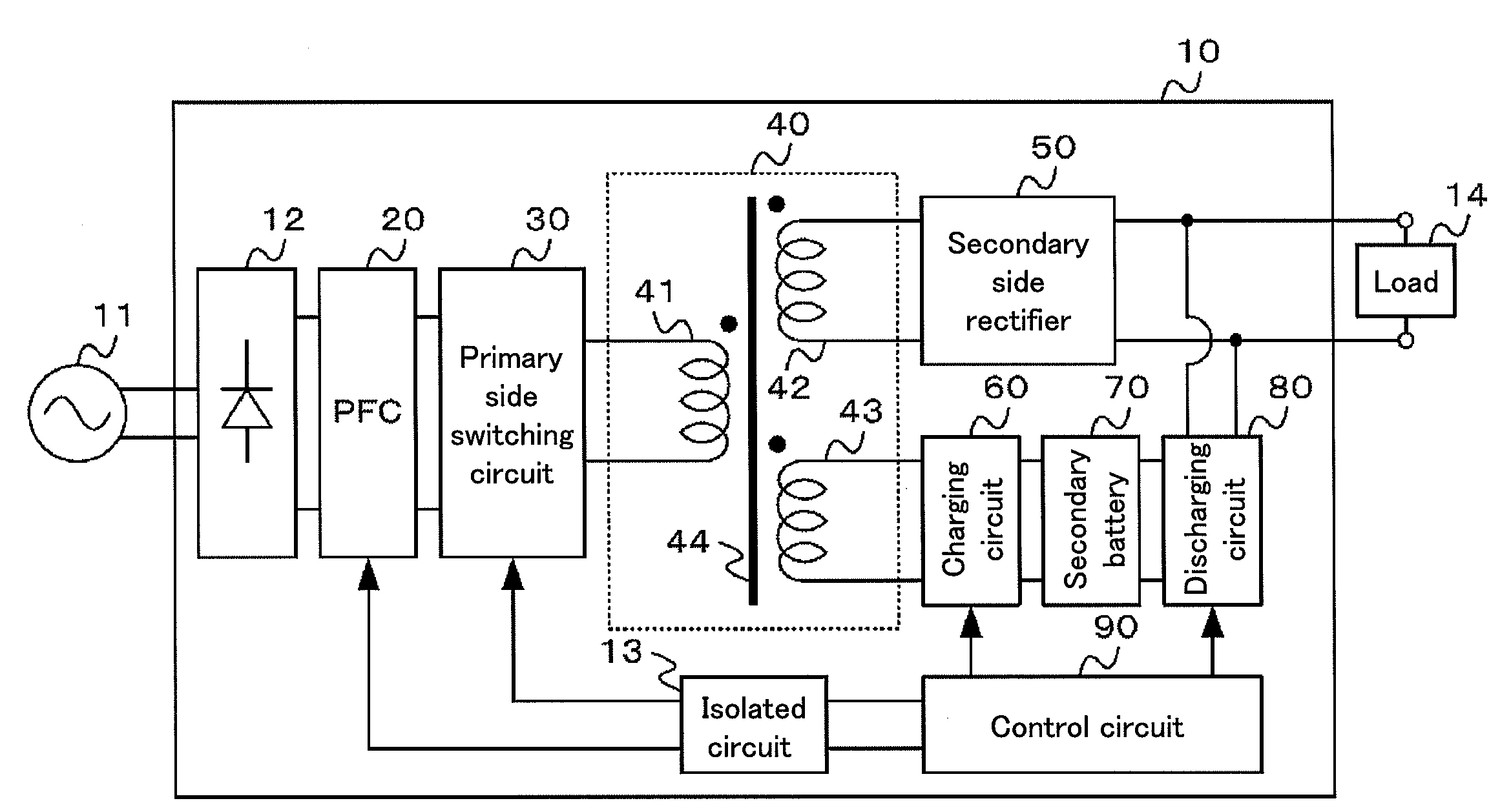
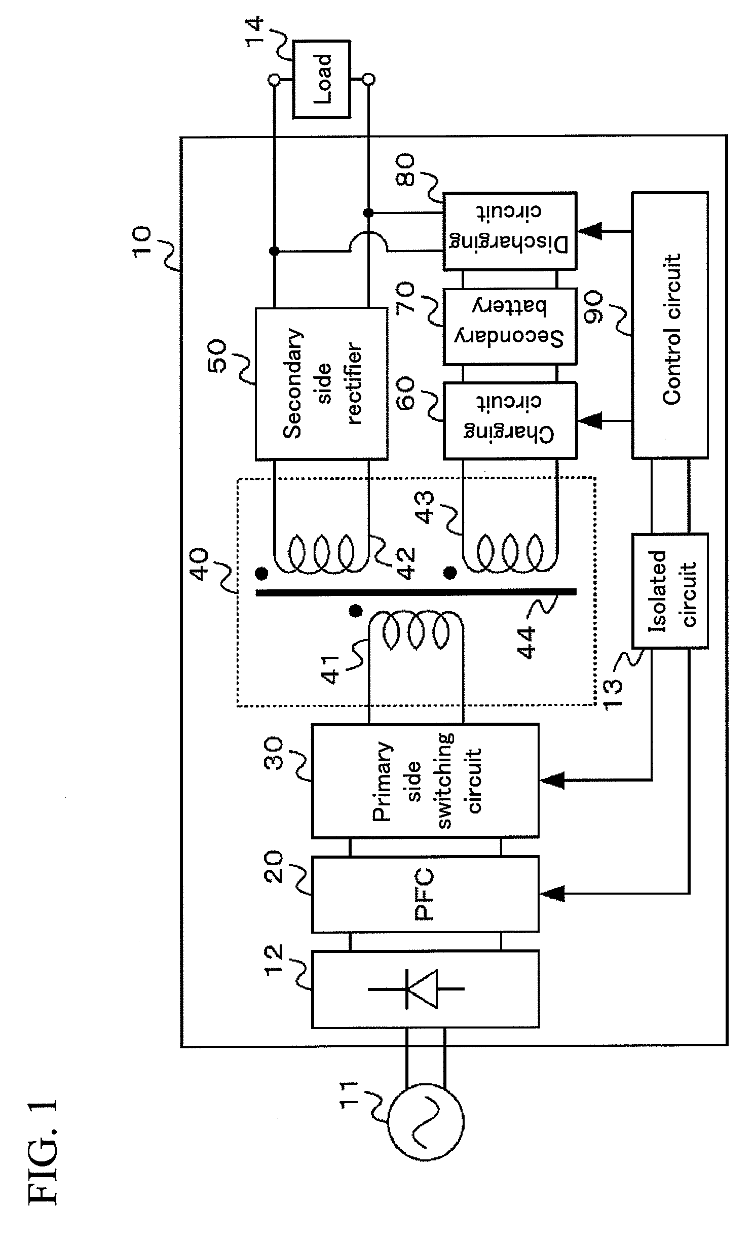
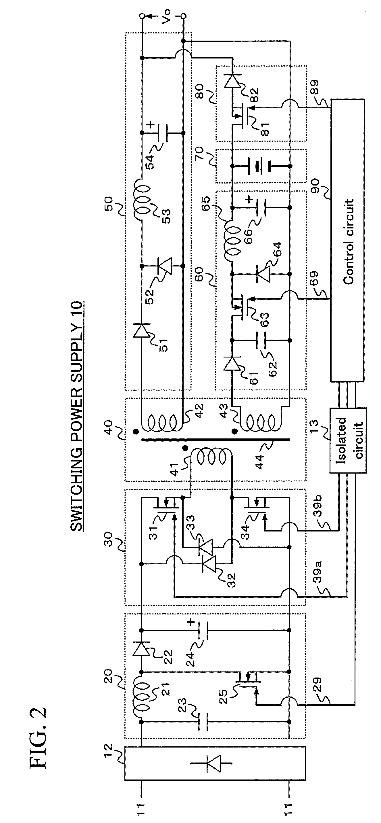
[0020]FIG. 1 is a block diagram showing a configuration of a switching power supply 10 according to an embodiment of the present invention. The switching power supply 10 includes a full-wave rectifier 12, an isolated circuit 13, a PFC (Power Factor Correction) 20, a primary side switching circuit 30, a transformer 40, a secondary side rectifier 50, a charging circuit 60, a secondary battery 70, a discharging circuit 80, and a control circuit 90.

[0021]The full-wave rectifier 12 rectifies a voltage and current of a commercial AC power supply 11. The PFC 20 improves the power factor of the rectified voltage and current by switching the current rectified by the full-wave rectifier 12, according to a control signal input from the control circuit 90 via the isolated circuit 13.

[0022]The transformer 40 has a primary winding 41, a secondary winding 42, an auxiliary winding 43, and a core 44. The primary...


PUM


Abstract

To provide a smaller and more efficient switching power supply 10. The switching power supply 10 according to the present invention includes: a high frequency transformer 40; a primary side switching circuit 30 adapted to switch a current flowing through a primary winding 41 of the high frequency transformer 40 to thereby generate predetermined voltages in a secondary winding 42 and an auxiliary winding 43 of the high frequency transformer 40; a secondary side rectifier 50 adapted to rectify a voltage generated in the secondary winding 42 of the high frequency transformer 40 to supply the rectified voltage to a load; a charging circuit 60 adapted to rectify a current flowing through the auxiliary winding 43 of the high frequency transformer 40 and switch the rectified current to thereby charge a secondary battery 70 at a constant current; and a switch 80 provided between the secondary battery 70 and the load, and supplies, when the voltage supplied to the load is interrupted, the voltage of the secondary battery 70 to the load without via the high frequency transformer 40.

Description

BACKGROUND OF THE INVENTION[0001]1. Field of the Invention[0002]The present invention relates to a switching power supply having a backup function.[0003]2. Background Art[0004]In Patent Document 1, there is disclosed a technique in which a tertiary winding 4b is newly provided for a high frequency transformer in a switching power supply, in which a backup power supply including a secondary battery 14, a charging circuit 3c, and a discharging circuit 3d is connected to the tertiary winding 4b, and in which the discharging circuit 3d is operated at the time of power failure to thereby enable the electric power of the secondary battery 14 to be supplied to a load via the tertiary winding 4b and a secondary winding 4c. By using the technique disclosed in Patent Document 1, it is possible to supply the electric power to the load at the time of power failure, so that an externally mounted UPS (Uninterruptible Power Supply) can be made unnecessary. Further, also when the primary side conve...

Claims


Application Information

Patent Timeline
Patent Type & Authority Applications(United States)
IPC IPC(8): H02J9/00H02J7/02H02M3/28
CPCH02M3/33561H02J9/061
Inventor TAKAHASHI, FUMIKAZUKANOUDA, AKIHIKOHAMAOGI, MASAHIROTAKAHASHI, YOSHIHIDE
Owner HITACHI INFORMATION & TELECOMM ENG LTD
Learn More