Light Activated RFID Tag

a technology of light-activated rfid tags and tags, which is applied in the field of rfid tags, can solve the problems that the older technology solar cells using glass substrates are not attractive to use in conjunction with such “sticker” tags

Active Publication Date: 2008-07-24
AMTECH SYST
View PDF16 Cites 59 Cited by
  • Summary
  • Abstract
  • Description
  • Claims
  • Application Information

AI Technical Summary

Benefits of technology

[0012]The present invention is for a radio frequency identification (RFID) device wherein power is supplied by conversion of light radiation, e.g., natural or artificial, to direct current (DC) energy using photovoltaic cells, e.g., solar cells. The photovoltaic cell could be used in place of one or more batteries, or in place of RF energy harvesting (rectification of the RF signals sent by the reader), or in combination with either or both of these known sources of energy. The RFID device is arranged for use with a remote interrogator unit, and comprises a circuit (preferably an integrated circuit) configured to send, in response to a signal (either unmodulated or modulated) received from the remote interrogator unit, a responsive signal (containing information to be sent from the tag to the reader) which may include identification information. The tag can store information such as the type and condition of the equipment of interest, fuel levels, time of day, temperature, ownership of the cargo, a manifest, vehicular traveled route information, or any other information that is useful to the operation of the business. This information can be updated as conditions change and subsequent communication with the tags (say, as the rail car travels along a track) can keep human operators apprised of the condition of the cargo, the point of entry of a vehicle in a toll road, the actions intended for the vehicle or object, etc. A communication antenna is electrically coupled to the tag electronic circuit and is provided for wireless communication with the remote interrogator unit.
[0013]One or more photovoltaic cells are provided for converting light radiation into electrical energy and providing power to the tag electronic circuit. A tag constructed using a photocell for operational power can have all the attributes and advantages of a traditional passive tag (unlimited life, small size, low cost, etc.) with the increased range of a battery-powered tag, and may be used for high performance transportation applications in countries with severe restrictions on RF power allowed to be sent by the reader.
[0015]In accordance with the present invention, utilization of the photovoltaic cell in combination with a passive RFID tag will increase the range at which such a tag can be read by the reader. Such utilization will also improve the sensitivity of the RFID tag by at least 20 dB (or better). This may enable the use of otherwise passive RFID tags in countries where limits are placed upon the use of RF power. Utilization of the photovoltaic cell in combination with a passive RFID tag will also increase the RF bandwidth of the broadcast of radio waves from the RFID tag in response to the reader. By utilizing sunlight or artificial light as a source of energy, the RFID tags of the present invention will have a longer life than RFID tags utilizing internal batteries for powering their circuits and / or supplying power for broadcasting.

Problems solved by technology

Older technology solar cells using glass substrates are not attractive to use in conjunction with such “sticker” tags because of cost and an inability to flex without breaking.

Method used


Image

  • Light Activated RFID Tag
  • Light Activated RFID Tag
  • Light Activated RFID Tag

Examples


Embodiment Construction

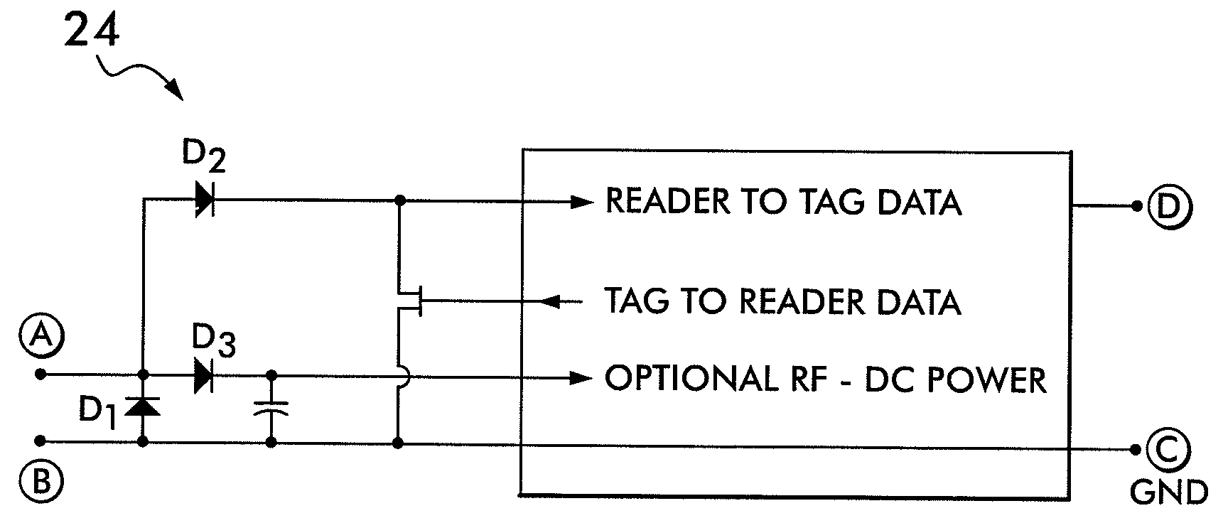
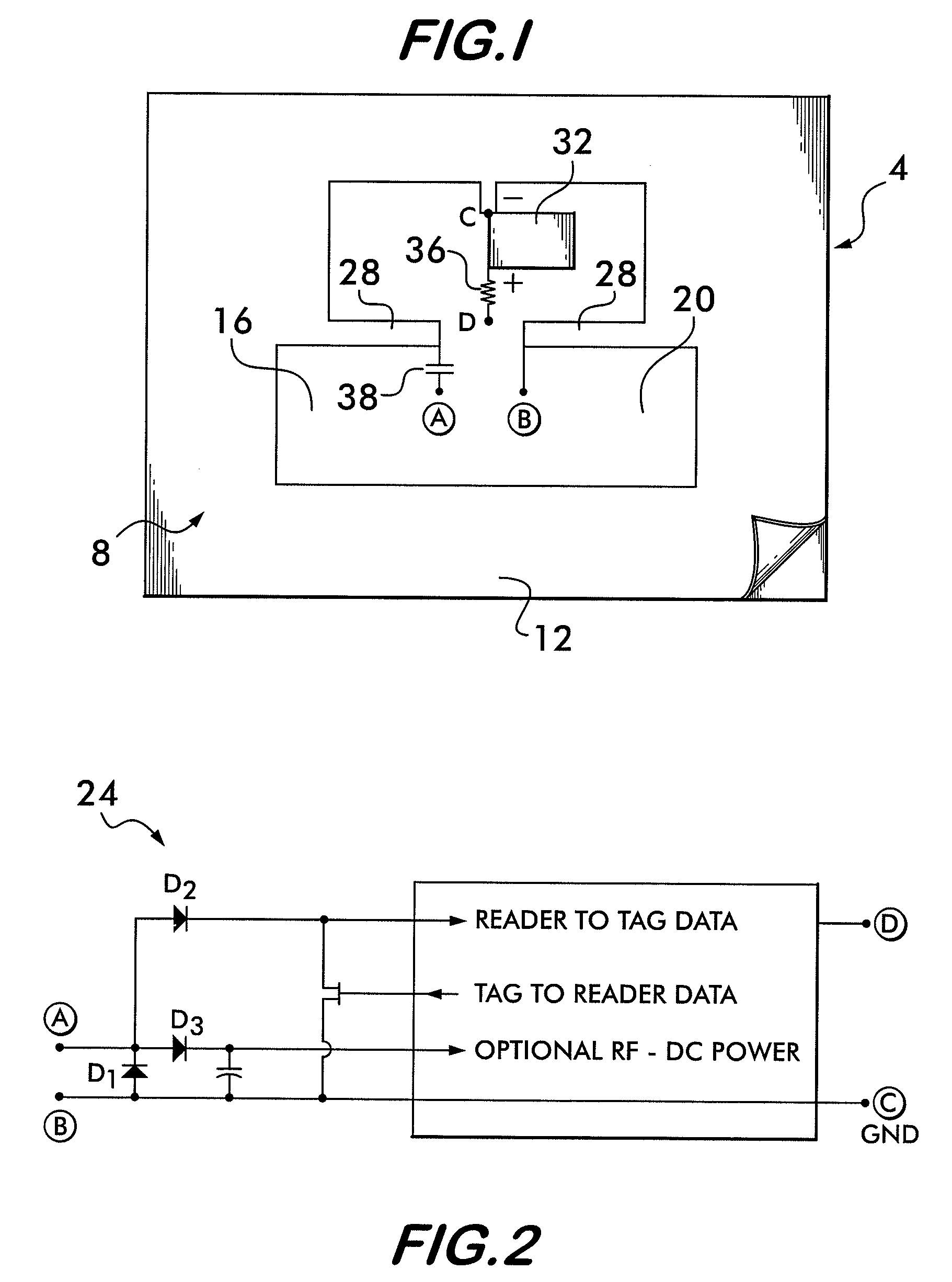
[0032]The RFID tag of the present invention is constructed using an electronic circuit, an antenna element, and a power source. Under the preferred embodiment, the electronic circuit is a single CMOS integrated circuit; the power source is a photovoltaic cell; and, the antenna element is constructed using all or part of the photovoltaic cell. Alternatively, the antenna element may be discrete and separate from the photovoltaic cell. The preferred embodiment uses a flexible solar cell, typically using amorphous silicon on a plastic substrate, made on a roll-to-roll process to increase manufacturing capacity and reduce cost.

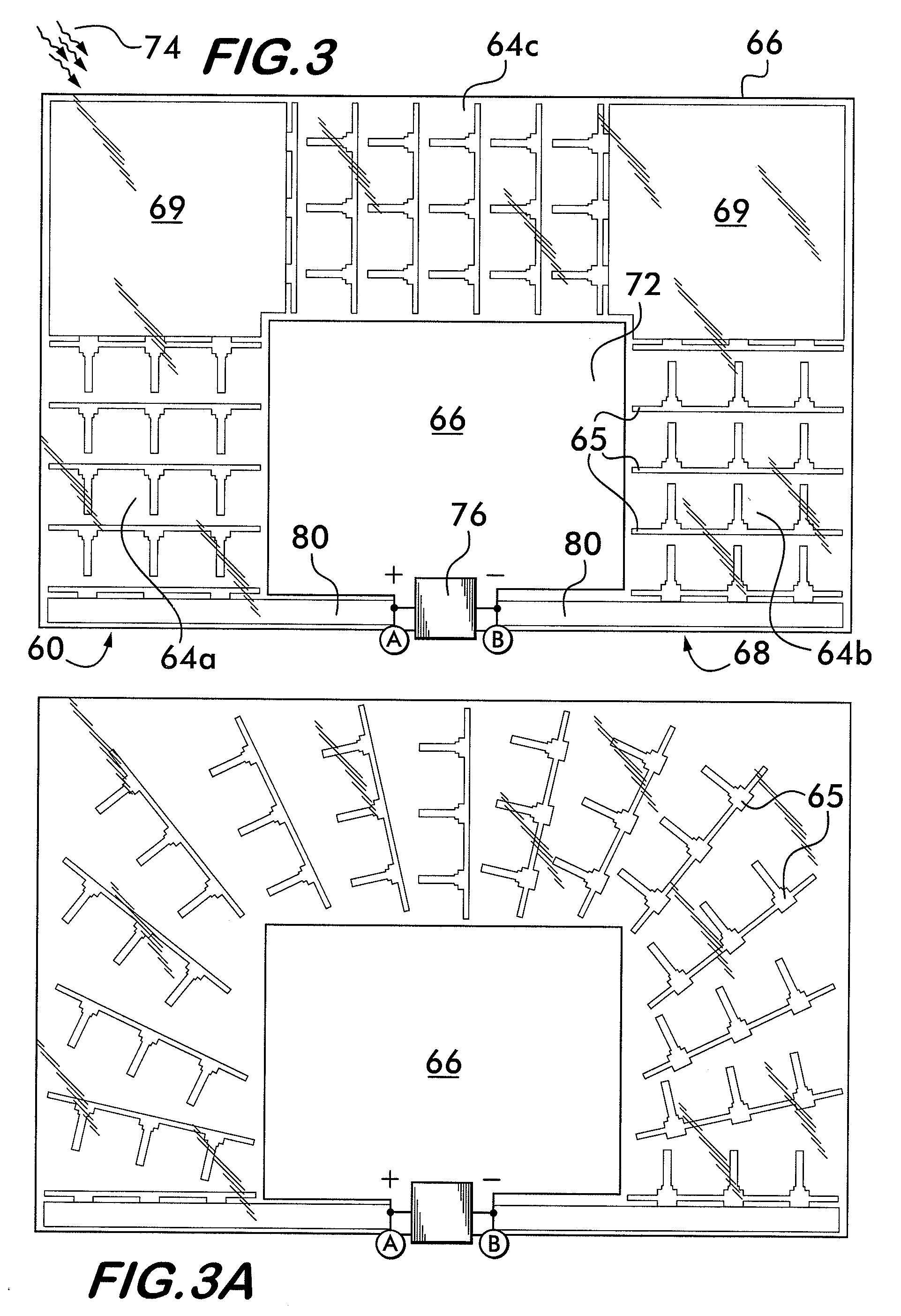
[0033]Solar radiation intensity in direct sunlight is about 1000 watts per square meter at the surface of the earth. The DC power requirements of an RFID chip may be as high as 100 microwatts for some operations such as writing EEPROM data. Thus, with full solar illumination, only a very small collection area is needed even with consideration of the limited efficie...


PUM


Abstract

A radio frequency identification (RFID) device is arranged for use with a remote interrogator unit. The RFID device comprises an integrated circuit configured to send, in response to a signal received from the remote interrogator unit or automatically, a responsive signal which includes identification information. A communication antenna is electrically coupled to the integrated circuit and is provided for wireless communication with the remote interrogator unit. At least one photovoltaic cell is provided for converting radiation into electrical energy and providing power to the integrated circuit. The photocell may be designed to form all or part of the RF antenna of the RFID device.

Description

RELATED APPLICATIONS[0001]This application claims priority to U.S. Provisional Application No. 60 / 881,519 filed Jan. 22, 2007, titled “Light-Activated RFID Tag.”FIELD OF THE INVENTION[0002]The present invention relates to radio frequency identification (RFID) tags, and more particularly, to an RFID tag wherein power is supplied by conversion of light radiation, e.g., natural or artificial, to direct current (DC) energy using photovoltaic cells, e.g., solar cells.BACKGROUND OF INVENTION[0003]RFID (radio frequency identification) is an automatic identification technology whereby digital data encoded in an RFID tag is captured by a reader using radio waves. RFID tags consist of an integrated circuit (IC) attached to an antenna, plus some protective packaging (like a plastic card) as determined by the application requirements. Tags also sometimes are called “transponders.” Data is stored in the integrated circuit and sent through the antenna to a reader. Prior art RFID tags are either “...

Claims


Application Information

Patent Timeline
Patent Type & Authority Applications(United States)
IPC IPC(8): G08B13/14
CPCG06K19/07749G06K19/0704
Inventor LANDT, JEREMYBURNETT, MATTHEWYOUN, TAIGRAVELLE, KELLYJOHNSON, CHARLES A.
Owner AMTECH SYST
Why Eureka
Try Eureka