Method and Apparatus for Quadrifilar Antenna with Open Circuit Element Terminations

a quadrifilar antenna and open circuit technology, applied in the field of antennas, can solve the problems of increasing the demand for higher transmitter/antenna efficiency, increasing the power budget, and reducing the size of the antenna, so as to improve the reception performance and reduce the size

Active Publication Date: 2008-07-24
MAXTENA
View PDF2 Cites 53 Cited by
  • Summary
  • Abstract
  • Description
  • Claims
  • Application Information

AI Technical Summary

Benefits of technology

[0026]Based on this disclosure, a person of ordinary skill will readily identify various applications for antenna and antenna systems embodying the invention one or more of its aspects. Illustrative examples include satellite position location reception such as GPS terminals. These include, in particular, handheld GPS terminals, as these would especially benefit from the invention's improved reception performance and reduced size. These applications are only illustrative examples, as a wide range and variety of other applications are contemplated including, without limitation, transmission and reception within various mobile terminal (e.g., satellite based) communication systems.

Problems solved by technology

One is that terminals for satellite communications and other wireless applications are becoming smaller.
Further, power budgets are becoming tighter, which increases demand for higher transmitter / antenna efficiency.
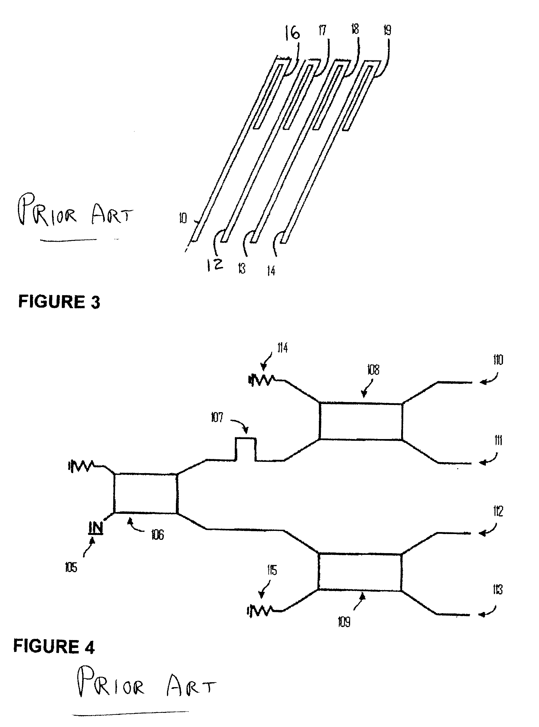
Further, although the known practical limit to which the prior art FIG. 3 arms can be folded is 0.5λ, it is also well known that if the length of the folded element (items 16, 17, 18 and 19) is greater than approximately than 0.18λ the interaction between the arms increases such that a practical and acceptable tuning of the antenna is not likely feasible in the known QHA arts.
One problem with this arrangement is that the characteristic impedance of the series distribution changes for each phased output and, therefore, each of the four antenna matching networks 118a, 118b, 118c, and 118d must be differently configured.
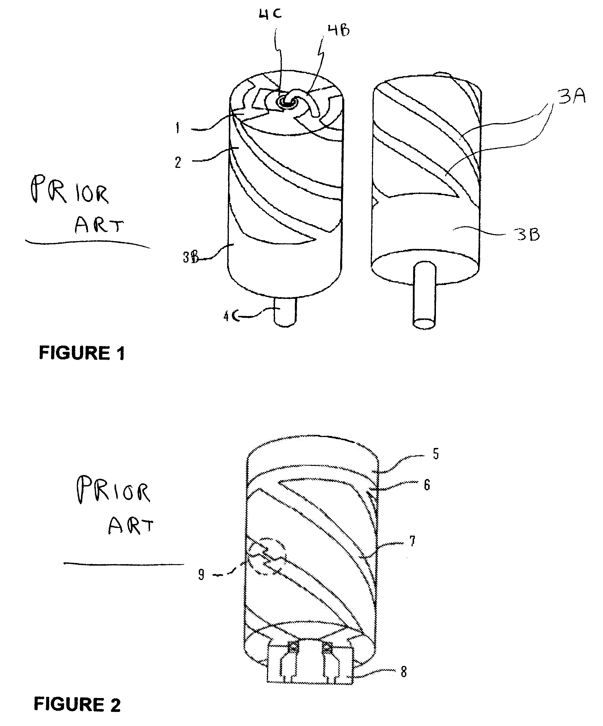
All of the FIG. 1-5 other prior art QHA have fundamental limitations, though, that will likely pose significant problems as demand for smaller size, higher performance antennas increases.
One problem is bandwidth.
Another problem is size.
Prior art QHA, when first introduced, provided size reduction over certain other antenna types, but further reduction in QHA size appears elusive.
There are fundamental problems, however, with this method.
In addition, loss is increased, reducing efficiency and gain.

Method used


Image

  • Method and Apparatus for Quadrifilar Antenna with Open Circuit Element Terminations
  • Method and Apparatus for Quadrifilar Antenna with Open Circuit Element Terminations
  • Method and Apparatus for Quadrifilar Antenna with Open Circuit Element Terminations

Examples


Embodiment Construction

[0049]The following detailed description refers to accompanying drawings that form part of this description. The drawings, though, show only illustrative examples of embodiments, and of arrangements and implementations for practicing the invention. Many alternative configurations and arrangements can, upon reading this description, be readily identified by persons skilled in the arts.

[0050]It will be understood that like numerals appearing in different ones of the accompanying drawings, either of the same or different embodiments of the invention, reference functional blocks or structures that are, or may be, identical or substantially identical between the different drawings.

[0051]It will be understood that, unless otherwise stated or clear from the description, the accompanying drawings are not necessarily drawn to scale.

[0052]It will be understood that particular examples are described and depicted, illustrating examples embodying one or more of the appended claims. It will be fu...


PUM


Abstract

A quadrifilar antenna having helical windings is fed by a phase shift feed network, each winding having an open circuit termination element, the phase shift feeding network having forward directional phase shift paths from a feed input to phase shift feed output ports, and having a first reverse directional transmission path from one or more of the phase shift feed output ports back to a first isolation port, and a second reverse directional transmission path from another one or more of the phase shift feed output ports back to a second isolation port, the first and second isolation ports isolated from the forward directional phase shift paths, and a differential termination impedance, floating from ground, connected the first and second isolation ports. Optionally, the differential termination impedance is frequency selective.

Description

CROSS-REFERENCE TO RELATED APPLICATIONS[0001]This application claims priority to U.S. Provisional Application Ser. No. 60 / 869,242, filed Dec. 8, 2006, which is hereby incorporated by reference.FIELD OF THE INVENTION[0002]The invention relates to antenna and, more particularly, quadrifilar antenna having helical conductor elements.BACKGROUND OF THE INVENTION[0003]Demand for smaller, higher performance, simpler and cheaper antennas continues to increase. The demand is due to multiple factors. One is that terminals for satellite communications and other wireless applications are becoming smaller. Another factor is that crowding of antennas continues to increase, both in space and frequency, increasing demand for improved antenna selectivity, in polarity and frequency. Further, power budgets are becoming tighter, which increases demand for higher transmitter / antenna efficiency. Further, particularly for hand held devices—as these tend to move relative to human bodies—demand for antennas...

Claims


Application Information

Patent Timeline
Patent Type & Authority Applications(United States)
IPC IPC(8): H01Q1/36G01R29/08H01Q21/00
CPCH01Q11/08
Inventor LICUL, STANISLAVMARKS, JEREMYSTUTZMAN, WARREN L.
Owner MAXTENA
Why Eureka
Try Eureka