Temperature dependent back-bias for a memory array

a memory array and temperature-dependent technology, applied in static storage, digital storage, instruments, etc., can solve the problems of imbalance at high temperature, sram design becoming increasingly difficult to have robustness,

Active Publication Date: 2008-07-24
TEXAS INSTR INC
View PDF12 Cites 30 Cited by
  • Summary
  • Abstract
  • Description
  • Claims
  • Application Information

AI Technical Summary

Problems solved by technology

It is becoming increasingly difficult to have an SRAM design that is robust for the overall conditions in which it is required to operate.
If there is a good balance between SNM and Vtrip at low temperature, there will be an imbalance at high temperature, generally.

Method used


Image

  • Temperature dependent back-bias for a memory array
  • Temperature dependent back-bias for a memory array
  • Temperature dependent back-bias for a memory array

Examples


Embodiment Construction

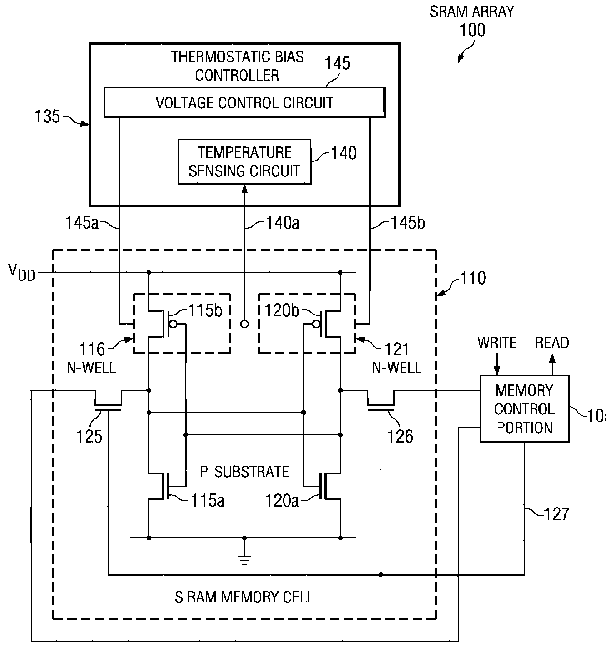
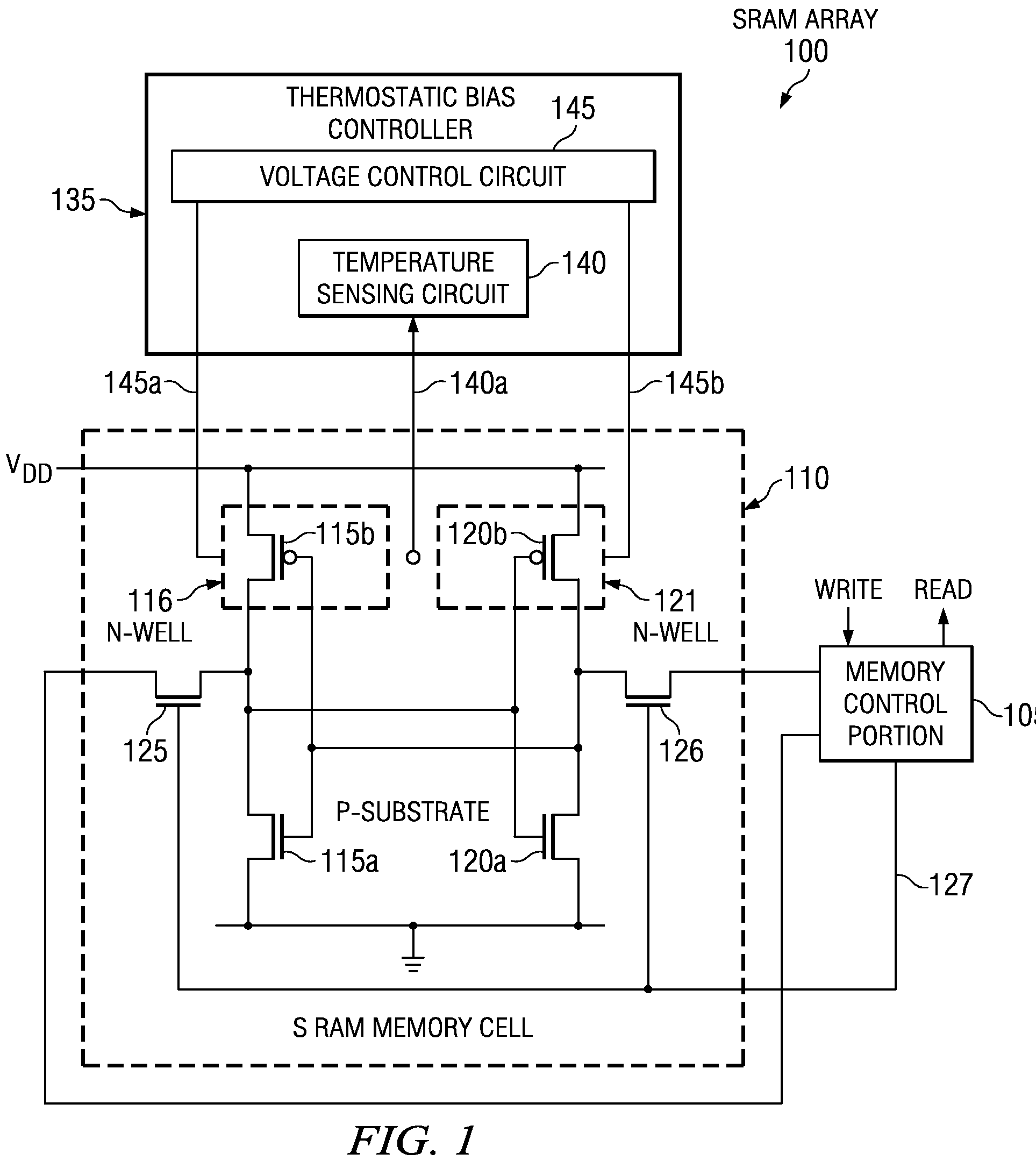
[0021]FIG. 1 illustrates an embodiment of an integrated circuit 100 constructed according to the principles of the present invention. The integrated circuit 100 includes a memory array, which is an SRAM array in the illustrated embodiment. The SRAM array has a plurality of SRAM memory cells, wherein a SRAM memory cell 110 is typical, that are coupled to a memory control portion 105. The memory control portion 105 provides read / write access for the SRAM array. The SRAM memory cell 110 consists of first and second CMOS inverters 115a / 115b and 120a / 120b that are cross-coupled to form a memory element, as shown. First and second NMOS transistors 115a, 120a operate as pull-down transistors, and first and second PMOS transistors 115b, 120b operate as pull-up transistors. The SRAM memory cell 110 also includes first and second n-wells 116, 121 that contain the first and second PMOS transistors 115b, 120b and are formed in a p-substrate containing the first and second NMOS transistors 115a,...


PUM


Abstract

The present invention provides a thermostatic bias controller for use with a memory array. The thermostatic bias controller includes a temperature sensing circuit configured to sense a temperature associated with the memory array. The thermostatic bias controller also includes a voltage control circuit coupled to the temperature sensing circuit and configured to provide a bias voltage to at least one back-gate of the memory array based on the temperature.

Description

TECHNICAL FIELD OF THE INVENTION[0001]The present invention is directed, in general, to semiconductor memory devices and, more specifically, to a thermostatic bias controller, a method of operating a thermostatic bias controller and a memory array employing the controller or the method.BACKGROUND OF THE INVENTION[0002]A static random access memory (SRAM) array employs a collection of cross-coupled CMOS inverters as memory elements having NMOS and PMOS transistors. Typically, the NMOS transistors are used as pull-down devices, and the PMOS transistors are used as pull-up devices. The NMOS transistors are contained in a p-substrate and the PMOS transistors are contained in an n-well within the p-substrate.[0003]It is becoming increasingly difficult to have an SRAM design that is robust for the overall conditions in which it is required to operate. Two key parameters affecting this realm are the static noise margin (SNM), which is its robustness against upset and the trip voltage (Vtri...

Claims


Application Information

Patent Timeline
Patent Type & Authority Applications(United States)
IPC IPC(8): G11C16/04
CPCG11C5/143G11C11/413G11C11/412
Inventor HOUSTON, THEODORE W.MARSHALL, ANDREW
Owner TEXAS INSTR INC
Why Eureka
Try Eureka