Voltage-adder LED driver

Inactive Publication Date: 2002-02-19
LEDI LITE
View PDF6 Cites 23 Cited by
  • Summary
  • Abstract
  • Description
  • Claims
  • Application Information

AI Technical Summary

Problems solved by technology

DC drive is not suitable for a high-efficiency system, and blinking effect is not suita

Method used


Image

  • Voltage-adder LED driver
  • Voltage-adder LED driver
  • Voltage-adder LED driver

Examples


Embodiment Construction

:

The present invention will now be described with reference to the drawing figures in sufficient detail to enable one normally skilled in the art to practice the invention. Before explaining at least one embodiment of the invention in detail, it is to be understood that the invention is not limited in its application to the details of construction and the arrangement of the components set forth in the following description or illustrated in the drawing. The invention is capable of other embodiments or of being practiced or carried out in various ways. Also, it is to be understood that the phraseology and terminology employed herein is for the purpose of description and should not be regarded as limiting.

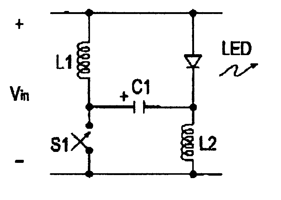
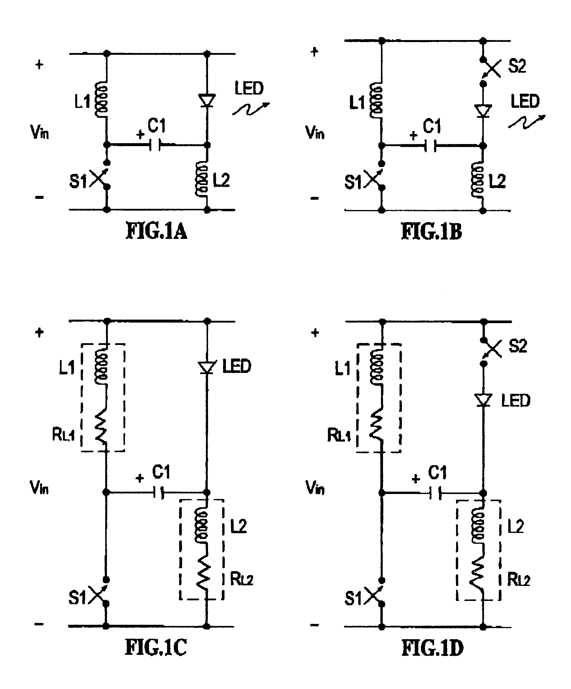
FIG. 1A shows the basic voltage-adder circuit driving a LED. The circuit comprises a switch, shown here, implemented by switch S1, and the network L1, C1, L2, driving the LED, LED.

S1 is normally-open, for a relatively long off-time, during which off-time, C1 charges through L1 and L2...


PUM


Abstract

A voltage-adder circuit, which adds the charge stored on a capacitor during a switch off-time, to the voltage of the input battery/power-supply, to provide an output voltage greater than the input voltage. The circuit is especially well-suited for use as an LED driver, and may be also used as a voltage booster for low-voltage electronic circuitry, such as electronic watches; as a back-bias generator for use inside integrated circuits; and, as a gate-bias-voltage generator, for use with depletion-mode GaAsFETs, such as are used in the transmitters of cellular telephones. The circuit obtains high efficiency operation by the use of inductors to charge a storage capacitor. Switches may be added. The invention includes a novel self-operating switch.

Description

Light-emitting diodes (LED's) are useful as an illumination source in signs for example, in simple house-number signs. It is desirable that the illumination source be reliable, and have high efficiency, both in terms of light output, and with respect to low power consumption from the power source. Also, low cost is important, in order to have the largest possible market for any product. For the house number sign application, an AC line-operated power source is undesirable, due to both inconvenience and cost.In response to this need, a high-efficiency, low power consumption, low-cost, LED light source is provided, which is battery-operated, operating from one cell. The inventive voltage-adder, LED driver circuit provides an increased voltage, greater than the battery voltage, for powering the load, in this application, a LED.The inventive voltage-adder circuit may also be used for providing an increased supply voltage to other circuitry having such a need. Additional applications inc...

Claims


Application Information

Patent Timeline
IPC IPC(8): H02M3/04H05B33/02H02M3/155H05B33/08H05B44/00
CPCH02M3/155H05B33/0815Y02B20/346H05B45/37Y02B20/30
Inventor FILIPOVSKI, MENACHEM
Owner LEDI LITE
Why Eureka
Try Eureka