Temperature measurement using changes in dielectric constant and associated resonance

Inactive Publication Date: 2008-07-24
MEGGITT SA
View PDF3 Cites 14 Cited by
  • Summary
  • Abstract
  • Description
  • Claims
  • Application Information

AI Technical Summary

Benefits of technology

[0013]The present invention implements a methodology for measuring temperature within high temperature environments by recognizing the change in dielectric constant of a resonant device, such as a patch antenna, with the use of appropriate microwave electronics, such as a network analyzer. The inventive technique is typically implemented with a patch antenna or other similar dielectric-based antenna, having an antenna radiating element and a dielectric subs

Problems solved by technology

Typical design values represent worse case scenarios and therefore, it can be difficult to accurately determine the operating temperature of the probe.
Embedding thermocouples or other temperature measurement devices within the antenna is possible, however, it represents additional complexity

Method used


Image

  • Temperature measurement using changes in dielectric constant and associated resonance
  • Temperature measurement using changes in dielectric constant and associated resonance
  • Temperature measurement using changes in dielectric constant and associated resonance

Examples


Embodiment Construction

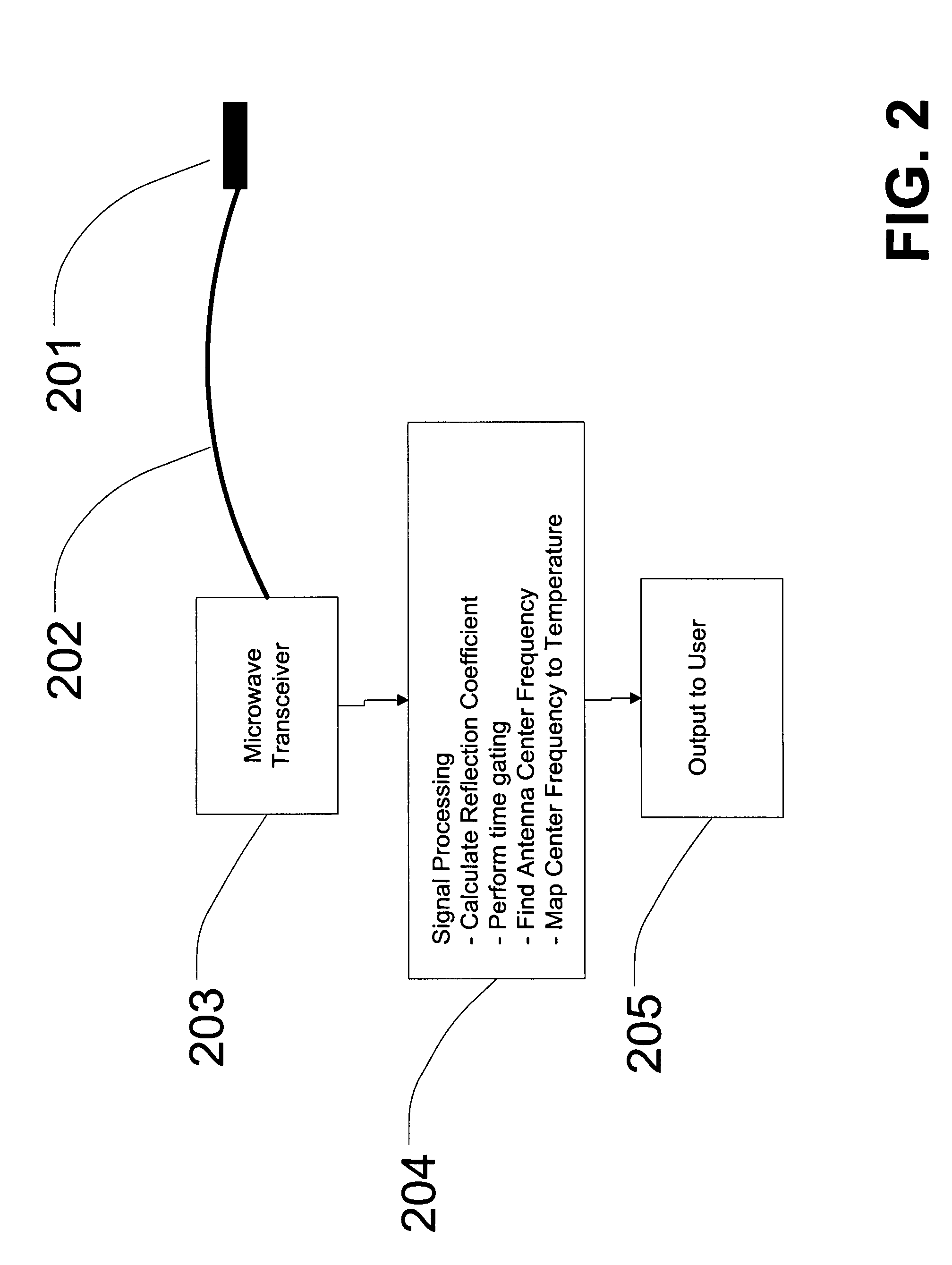
[0024]Exemplary embodiments of the present invention provide for a method of measuring temperature by measuring the change in dielectric constant of an antenna having a dielectric material and a radiating element, typically a patch antenna, within a high temperature environment. For the purpose of this disclosure, a high temperature environment is defined by an environment having a temperature of or greater than 600° F.

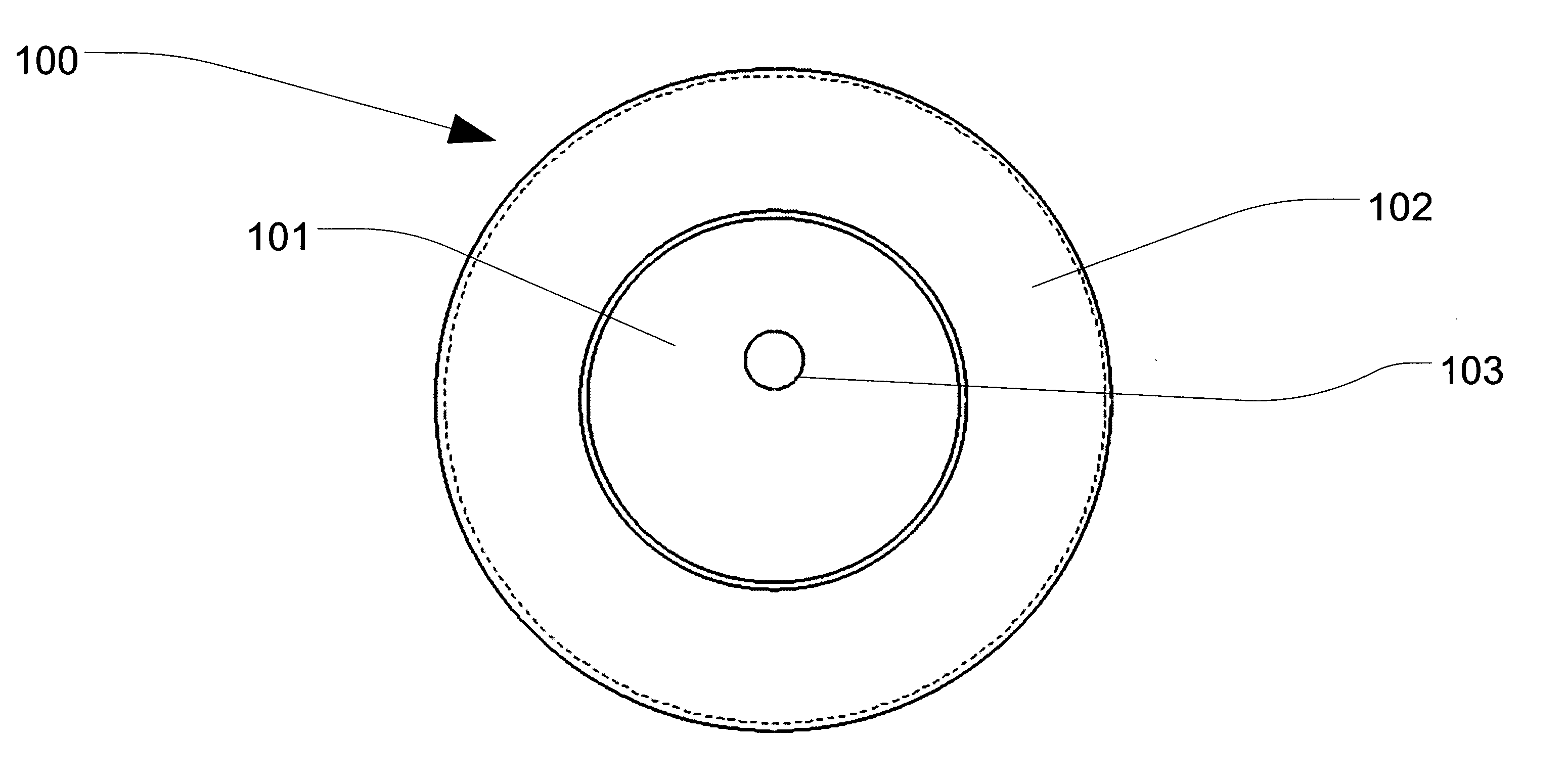
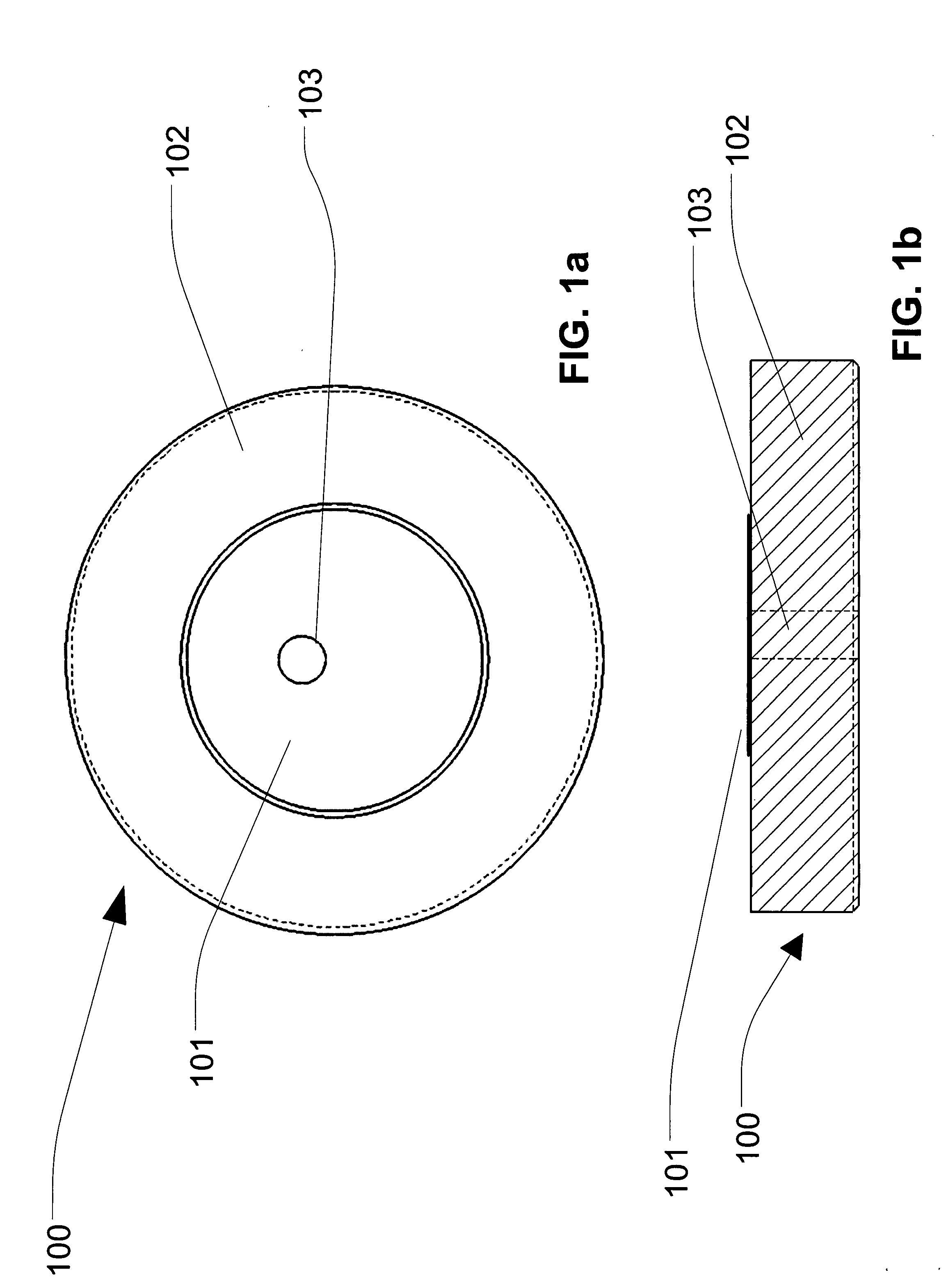
[0025]Exemplary embodiments of the present invention will now be described more fully hereinafter with reference to FIGS. 1-5, in which embodiments of the invention are shown. FIG. 1a is the top view of an exemplary implementation of a patch antenna with metallization applied using a thick film or thin film process in accordance with one embodiment of the present invention. FIG. 1b is the side view of an exemplary implementation of a patch antenna with metallization applied using a thick film or thin film process in accordance with one embodiment of the present invent...


PUM


Abstract

A temperature measurement technique for calculating a temperature in a high temperature environment by monitoring a change in resonant frequency of a resonant structure loaded with a dielectric material. A response curve for a reflection coefficient S11 associated with the resonant structure is generated, typically by the use of a network analyzer connected to the resonant structure via a cable. A minimum point for the response curve is identified to detect the resonant frequency for the resonant structure. A calibration map is applied to the minimum point to identify a temperature associated with the resonant frequency of the resonant structure. The temperature associated with the resonant frequency of the resonant structure represents the temperature of the high temperature environment.

Description

RELATED APPLICATION[0001]Applicants claim priority under 35 U.S.C. 119 to an earlier-filed provisional patent application, U.S. Provisional Patent Application Ser. No. 60 / 791,810, filed on Apr. 13, 2006, entitled “Measuring Temperature Via Center Frequency Drift”. The subject matter disclosed by this provisional patent application is fully incorporated within the present application by reference herein.TECHNICAL FIELD[0002]The present invention relates to temperature measurement and more particularly to the design and use of a temperature measurement device within high temperature environments.BACKGROUND OF INVENTION[0003]Temperature measurement is normally performed by measuring the change in some quantity proportional to temperature. Most often in industrial environments, this is performed using a thermocouple. A thermocouple will use the voltage difference between two dissimilar metals and map that voltage to a temperature using a calibration curve. Other measurement techniques m...

Claims


Application Information

Patent Timeline
IPC IPC(8): G01K11/22
CPCG01K7/32G01K15/00G01K11/006
Inventor BILLINGTON, SCOTTGEISHEIMER, JONATHANHOLST, THOMAS
Owner MEGGITT SA
Why Eureka
Try Eureka