Image processing apparatus and method thereof

a processing apparatus and image technology, applied in the field of image processing apparatus and method thereof, can solve the problems of image quality deterioration, image deterioration in a part, image quality deterioration,

Inactive Publication Date: 2008-07-24
CANON KK
View PDF12 Cites 15 Cited by
  • Summary
  • Abstract
  • Description
  • Claims
  • Application Information

AI Technical Summary

Benefits of technology

[0011]One aspect of the present invention is to...

Problems solved by technology

However, since lossy coding that executes DCT conversion of this type compresses data by limiting high-frequency components, noise called mosquito noise is generated at an edge part of an image or around a moving object, thus causing image quality deterioration of the decoded image.
However, in the above related art, since filtering processing for mosquito noise removal is applied to the edge part of an image signal irrespective of the presence/absence of mosquito noise in the image signal, an image deteriorates in a part where no mosquito noise is generated.
When an image includes a texture area including ...

Method used


Image

  • Image processing apparatus and method thereof
  • Image processing apparatus and method thereof
  • Image processing apparatus and method thereof

Examples


first embodiment

Other Arrangements of First Embodiment

[0080]In the first embodiment, the size of a block to be processed is defined by 4×4 pixels, but other sizes such as 8×4, 4×8, 8×8, and the like may be used.

[0081]The processes of the edge intensity measuring instruments 100 and 101 use the Sobel filters shown in FIGS. 8A and 8B, but other differential filters may be used.

[0082]The horizontal filter 106 and 2D filter 107 use the operators shown in FIGS. 9A and 9B, but may use other operators.

[0083]Furthermore, the frame memory stores a frame image. Alternatively, a field memory which stores a field image may be used.

[0084]The thresholds EP1 and EP2 in the noise removal flag calculator 103 need not be fixed but may be variably set for respective frames.

[0085]As described above, according to the first embodiment, in a moving image coding apparatus and method thereof including an interlaced signal, a part in image data where coding noise such as mosquito noise is generated can be adequately detecte...

second embodiment

Other Arrangements of Second Embodiment

[0097]In the exemplary second embodiment, the size of a block to be processed is defined by 4×4 pixels, but other sizes such as 8×4, 4×8, 8×8, and the like may be used.

[0098]The processes of the edge intensity measuring instruments 100 and 101 use the Sobel filters shown in FIGS. 8A and 8B, but other differential filters may be used.

[0099]In place of the ε filter, other edge preservation filters may be used.

[0100]The frame memory stores a frame image. Alternatively, a field memory which stores a field image may be used.

[0101]The thresholds EP1 and EP2 in the noise removal flag calculator 103 may not be fixed but may be variably set for respective frames.

[0102]As described above, according to the second exemplary embodiment, in a moving image coding apparatus and method thereof including an interlaced signal, a part in image data where coding noise such as mosquito noise is generated can be adequately detected. Since the edge preservation filter...

third embodiment

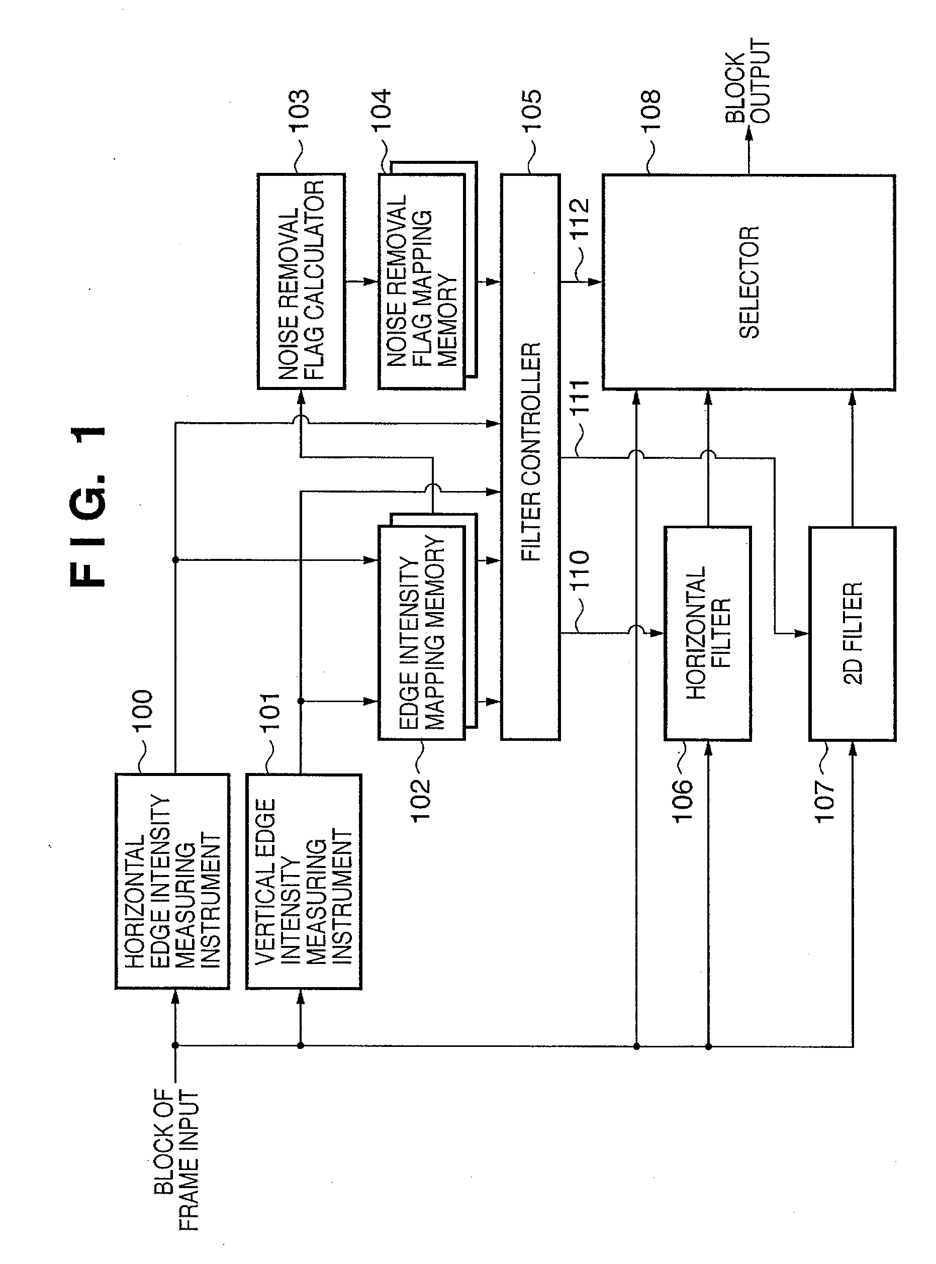
[0103]FIG. 14 is a block diagram showing the arrangement of principal part of an image processing apparatus according to a third exemplary embodiment of the present invention. Note that the third embodiment an 8×8 pixel size of luminance signals of an image and a 4×4 pixel size of color difference signals thereof as units of processing of image data, which are called object blocks.

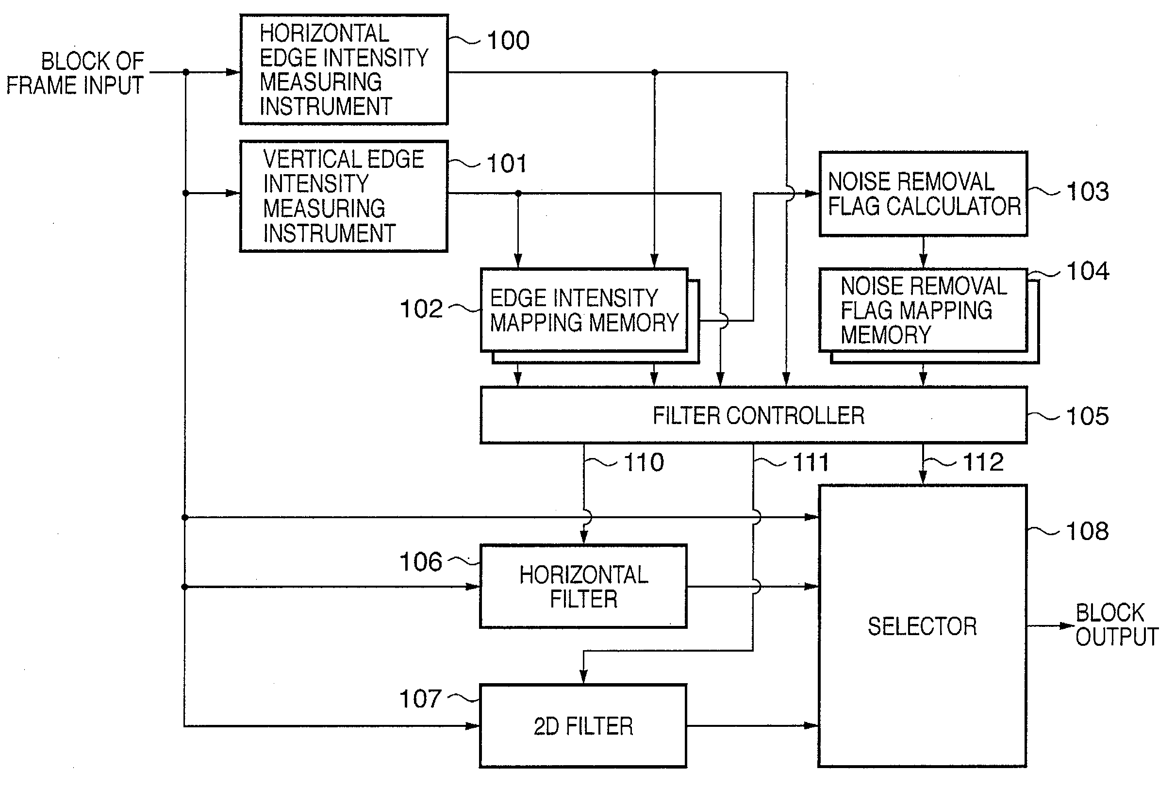
[0104]Referring to FIG. 14, a horizontal edge intensity measuring instrument 100 receives one block of luminance signals of an image, and measures the horizontal edge intensity of that block. A vertical edge intensity measuring instrument 101 receives one block of luminance signals of that image, and measures the vertical edge intensity of that block. This embodiment expresses the edge intensity for pixels of a block as the processing unit by an accumulated value of a Sobel filter. Operators of Sobel filters used in the third embodiment are the same as those in FIGS. 8A and 8B.

[0105]An edge intensity mappi...


PUM


Abstract

The intensities of horizontal and vertical edges of each block of luminance signals of an image are measured, and horizontal and vertical edge intensity data of respective blocks are stored for one frame in an edge intensity mapping memory. A noise removal flag used to specify a filtering block is calculated based on the edge intensity data, and is stored in a noise removal flag mapping memory. A filter controller controls whether or not to apply filtering processing to each block, specified by this noise removal flag, of the current frame of the image based on the horizontal and vertical edge intensity data of that block of the current frame and those of the corresponding block of the immediately preceding frame.

Description

BACKGROUND OF THE INVENTION[0001]1. Field of the Invention[0002]The present invention relates to an image processing apparatus and method thereof, which detect a noise containing part of an image obtained by decoding image data which has undergone frequency transformation and lossy compression coding by, e.g., an MPEG (Moving Picture Experts Group) scheme or the like, and remove that noise part.[0003]2. Description of the Related Art[0004]Conventionally, as image coding schemes, Motion JPEG, Digital Video, and the like as intraframe coding schemes, H.261, H.263, MPEG-1, and MPEG-2 using interframe predicting coding are available. In recent years, a coding scheme such as H.264 or the like is known. These coding schemes are internationally standardized by ISO (International Organization for Standardization) and ITU (International Telecommunication Union).[0005]MPEG-2 as a representative coding scheme is called lossy coding, and decoded data of encoded image data does not become the sa...

Claims


Application Information

Patent Timeline
IPC IPC(8): G06K9/40
CPCH04N19/61H04N19/86H04N19/42
Inventor OHIRA, TADASHI
Owner CANON KK
Why Eureka
Try Eureka