Supercharger with heat insulated gear case

a supercharger and gear case technology, applied in the direction of machines/engines, liquid fuel engines, rotary/oscillating piston pump components, etc., can solve the problems of catastrophic supercharger damage, limited problem, and inability to maintain high speed and load at high speed and load, and achieve the effect of low cos

Inactive Publication Date: 2008-07-24
GM GLOBAL TECH OPERATIONS LLC
View PDF5 Cites 31 Cited by
  • Summary
  • Abstract
  • Description
  • Claims
  • Application Information

AI Technical Summary

Benefits of technology

[0006]The present invention results from consideration of both practical and low cost

Problems solved by technology

The boosted air heats the gear case oil by forced convection/conduction through the aluminum bearing plate At high boost levels, this can lead to unacceptable gear case temperatures at continued high speeds and loads.
This in turn may require speed limits or boost trim to prevent gear case oil damage or seal damage th

Method used


Image

  • Supercharger with heat insulated gear case
  • Supercharger with heat insulated gear case
  • Supercharger with heat insulated gear case

Examples


Embodiment Construction

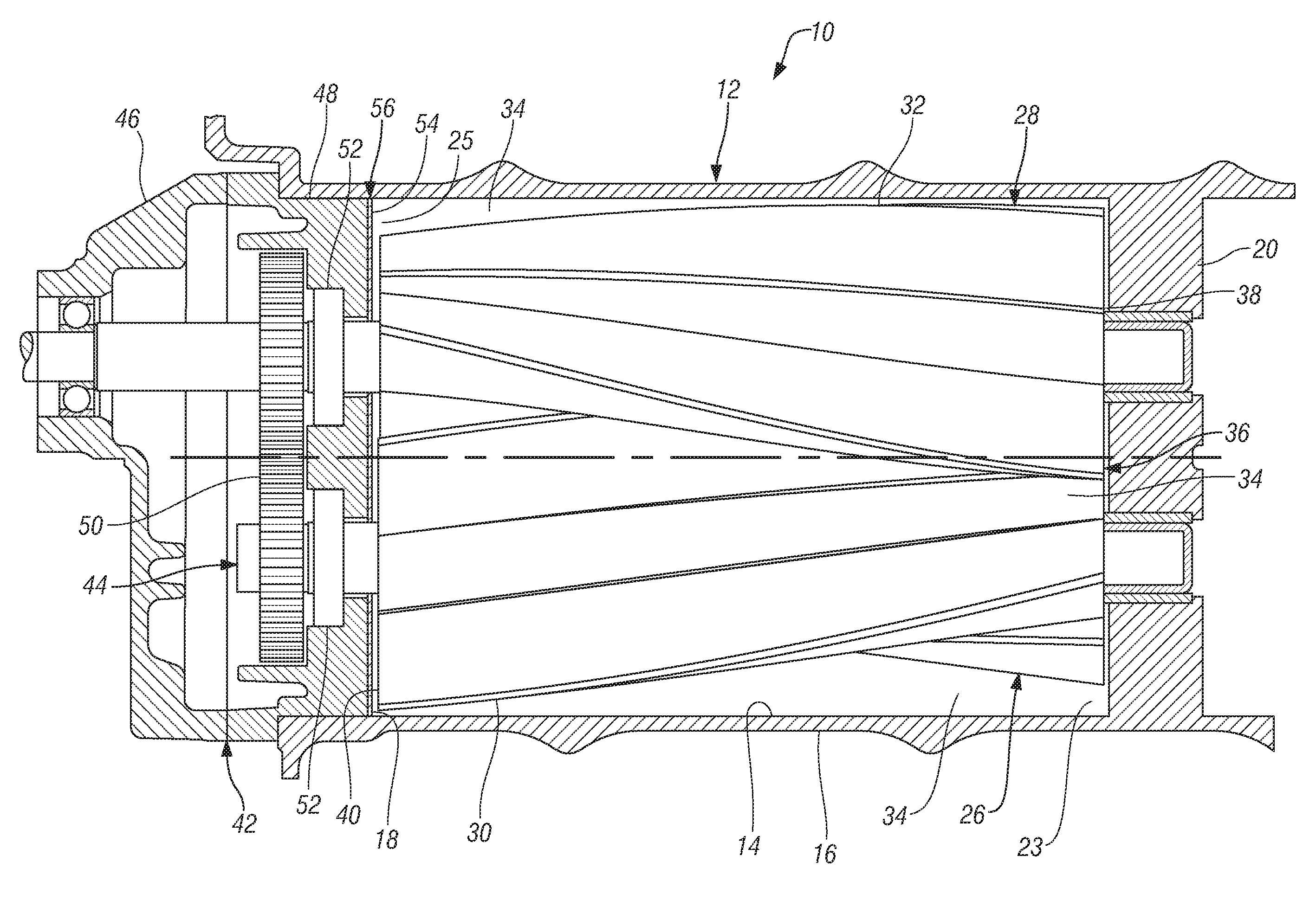
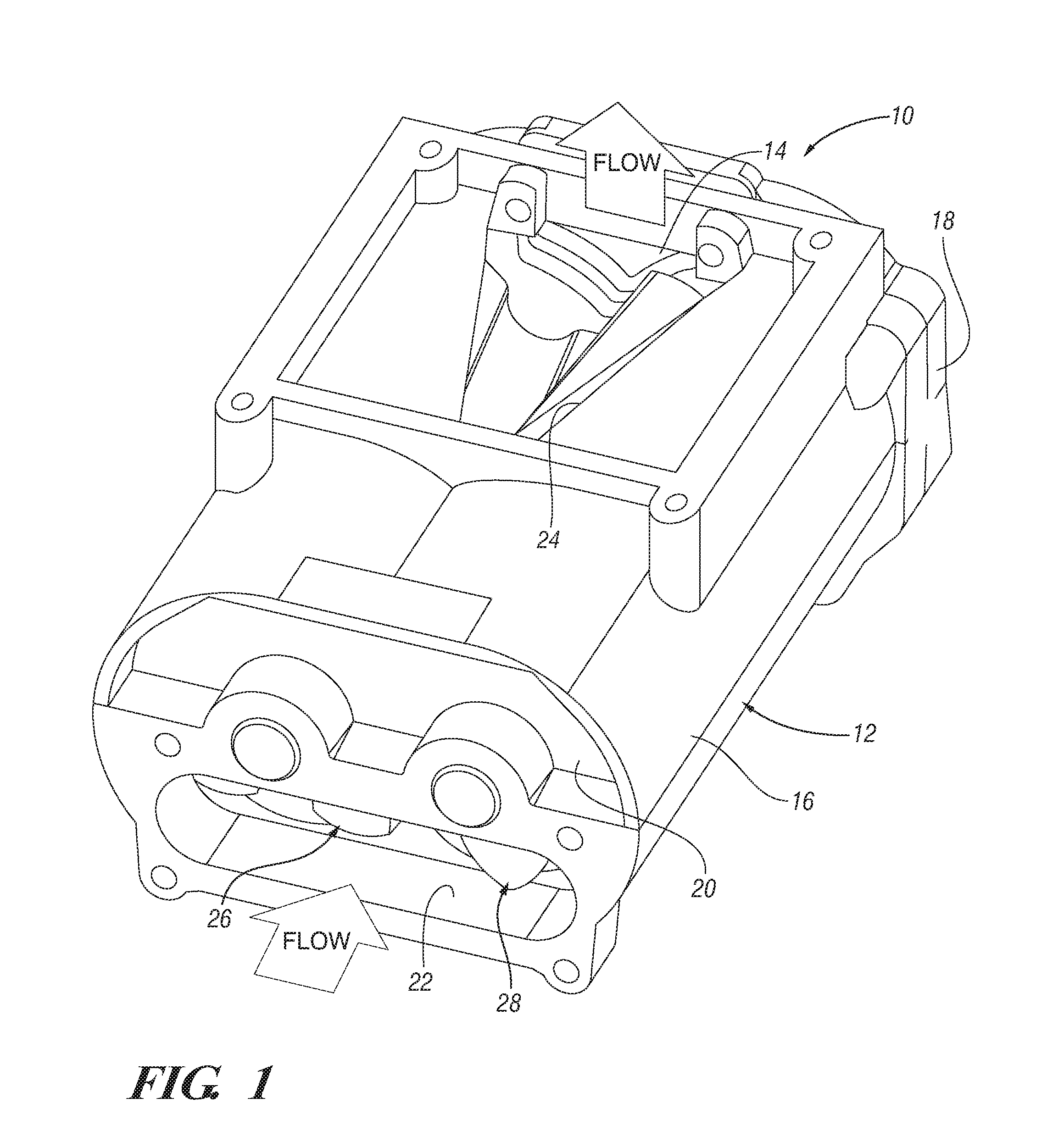
[0017]Referring first to FIG. 1 of the drawings in detail, numeral 10 generally indicates a positive displacement helical lobed compressor or supercharger according to the invention. Supercharger 10 includes a rotor housing 12 having an internal rotor cavity 14 defined by a surrounding wall 16 and front and rear end walls 18, 20 respectively. A generally rectangular inlet opening 22 in a lower portion of the rear end wall 20 communicates an inlet end 23 of the cavity 14 with a source of inlet air, not shown. A generally V-shaped outlet opening 24 extends through the surrounding wall 16 adjacent the front end wall 18 of the housing and communicates an outlet end 25 of the cavity 14 with a pressure charging air system, not shown.

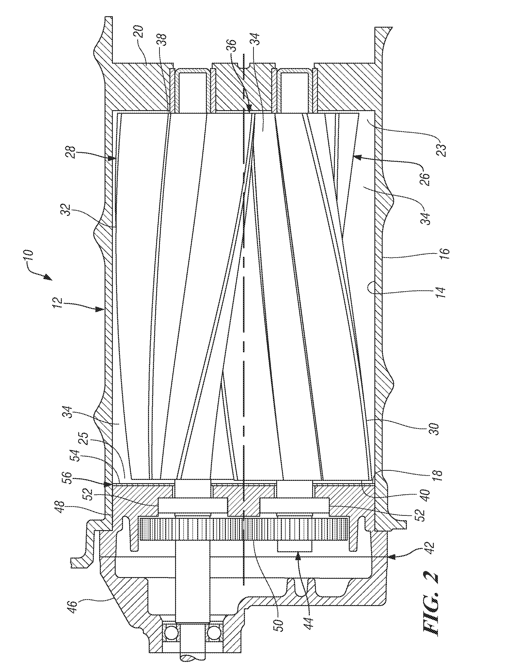
[0018]Within the cavity 14 there are rotatably mounted a pair of supercharger rotors 26, 28 having lobes 30, 32 with opposite helix angles, as is best shown in FIG. 2. The lobes 30, 32 of the rotors are interleaved in assembly to define with the housing helica...


PUM


Abstract

A positive displacement supercharger includes a housing having a rotor cavity. A pair of positive displacement rotors are oppositely rotatable in the rotor cavity and have interleaved helical lobes forming rotor chambers operative to carry air axially from an inlet end to an outlet end of the cavity. A gear case adjacent the rotor cavity is drivably connected with and supports the rotors, the gear case including a bearing housing having an end surface facing the rotor cavity and the outlet ends of the rotors. A heat insulating material is applied to the end surface of the bearing housing and is effective to reduce heat flow between the rotor cavity and the end surface of the bearing housing to effectively reduce lubricating oil temperatures in the gear case. The insulating material may be a ceramic plate fixed to the bearing housing end surface.

Description

TECHNICAL FIELD[0001]This invention relates to positive displacement compressors or superchargers, such as roots type or screw compressors utilized for automotive engine superchargers and other purposes.BACKGROUND OF THE INVENTION[0002]It is known in the art to utilize positive displacement compressors having lobed rotors for supercharging internal combustion engines and for providing compressed air for other purposes. Such a compressor used as an automotive supercharger may include a housing having a rotor cavity in which a pair of parallel rotors having interleaved lobes rotate to compress air drawn into one end of the housing and discharged through an opening in the cavity wall near an opposite end of the housing. The rotors may be belt driven by the engine through a pulley connected directly, or through a gear train, to the pair of rotors.[0003]Roots type and screw type compressors used on original equipment automotive engines are made with a bearing housing between the rotors a...

Claims


Application Information

Patent Timeline
IPC IPC(8): F01C21/06F01C1/16F01C1/24
CPCF04C18/086F04C18/126F05C2251/04F04C29/02F05C2203/08F04C18/16
Inventor PRIOR, GREGORY P.
Owner GM GLOBAL TECH OPERATIONS LLC
Why Eureka
Try Eureka