

Pattern formation method
a technology of pattern formation and substrate, applied in the direction of coating, optics, instruments, etc., can solve the problems of difficult formation of uniform orientation films, and droplets discharged on the substrate that sometimes do not spread uniformly on the substrate, etc., to achieve simplified pattern formation on the substrate and easy formation
- Summary
- Abstract
- Description
- Claims
- Application Information
AI Technical Summary
Benefits of technology
Problems solved by technology
Method used
Image

Examples
first embodiment
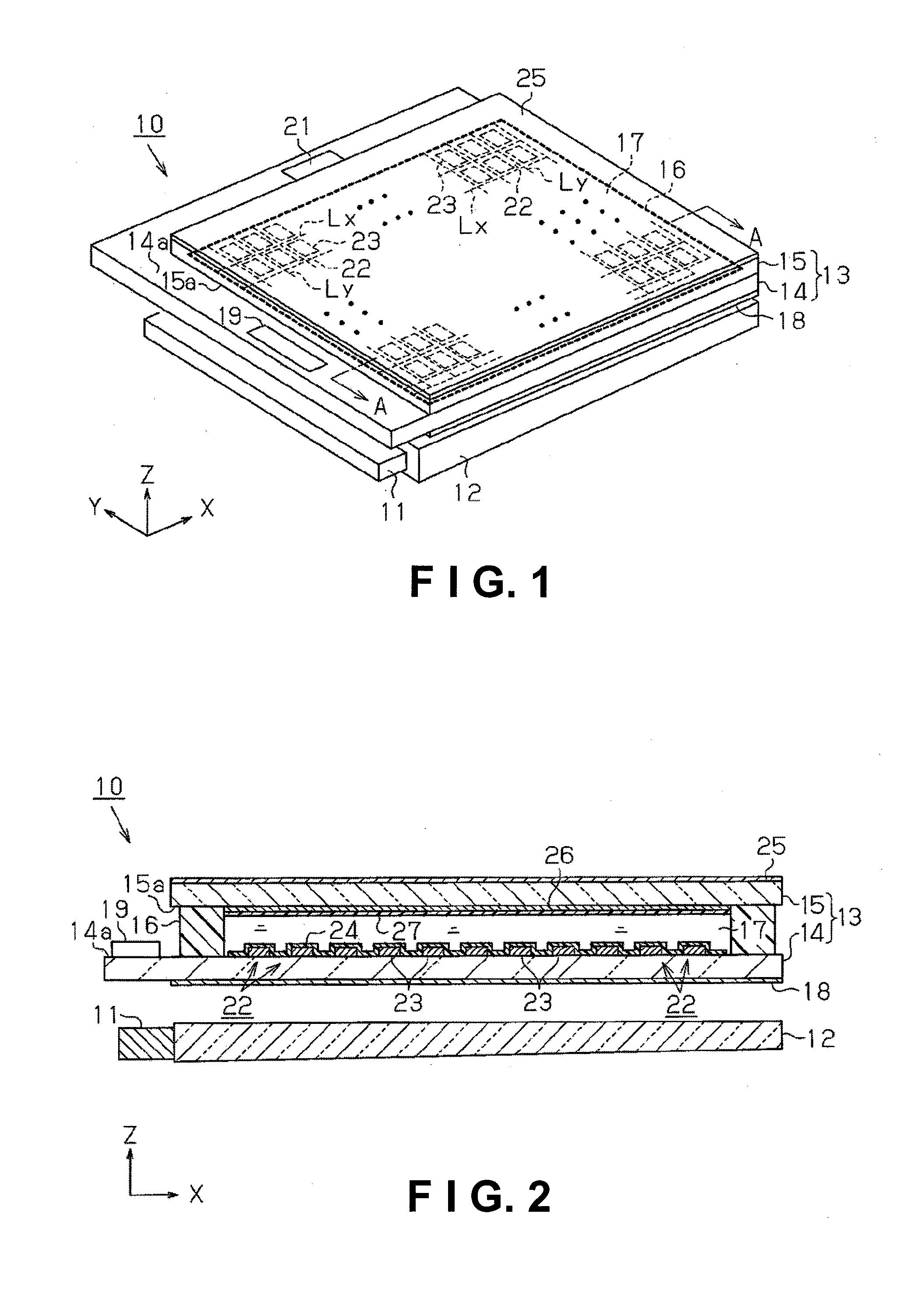
[0049]The first embodiment as a specific implementation of the present invention will be described hereinafter according to FIGS. 1 through 10. A liquid crystal display device 10 having an orientation film formed by the pattern formation method of the present invention will first be described. FIG. 1 is a perspective view showing the liquid crystal display device 10, and FIG. 2 is a sectional view along line A-A in FIG. 1.
[0050]In FIG. 1, an edge-light-type backlight 12 formed in a square plate shape having an LED or other light source 11 is provided to the lower side of the liquid crystal display device 10. A square plate-shaped liquid crystal panel 13 formed substantially the same size as the backlight 12 is provided above the backlight 12. The light emitted from the light source 11 is emitted towards the liquid crystal panel 13.
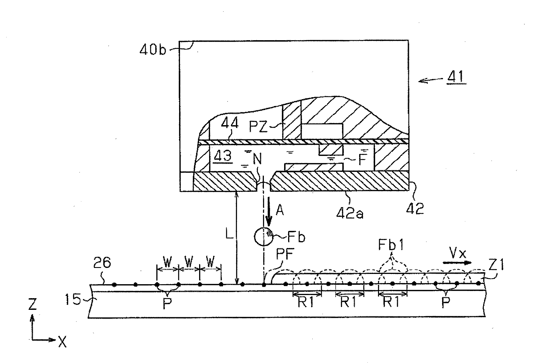
[0051]An element substrate 14 and an opposing substrate 15 that face each other are provided to the liquid crystal panel 13. As shown in FIG. 2, the eleme...
second embodiment
[0108]The second embodiment as a specific implementation of the present invention will be described hereinafter according to FIGS. 11 through 14. The present embodiment is a method for using a droplet discharge device to form a color filter on the opposing substrate of a liquid crystal panel.
[0109]The liquid crystal panel of the present embodiment is a large-sized liquid crystal panel in comparison to the first embodiment, but the structure of the element substrate is substantially the same. The structure of the droplet discharge device used in manufacturing is also substantially the same as that of the droplet discharge device 30 of the first embodiment, and description thereof is therefore omitted. To simplify the description, the reference numerals of the liquid crystal display device 10 of the first embodiment will be used.
[0110]The opposing substrate 60 will first be described based on FIGS. 11 and 12.
[0111]A color filter 61 is formed on the entire surface (surface on the side ...
third embodiment
[0127]The third embodiment as a specific implementation of the present invention will be described hereinafter.
[0128]The third embodiment as a specific implementation of the present invention will be described hereinafter according to FIGS. 14 and 15. The present embodiment is a method for forming the pixel electrodes of the element substrate in the second embodiment using a droplet discharge device. For convenience in the description, the reference numerals of the liquid crystal display device 10 of the first embodiment will be used. The same reference numerals are used for members that are the same as those in the first embodiment, and no description thereof will be given.
[0129]FIG. 14 is a sectional view in which the portion of the pixel electrode 23 as conductive wiring in an element substrate 70 is enlarged.
[0130]As shown in FIG. 14, an insulation layer 71 as a convex part composed of a silicon oxide film or the like is formed on the upper surface of the element substrate 70 be...
PUM
| Property | Measurement | Unit |
|---|---|---|
| Color | aaaaa | aaaaa |
| Hydrophilicity | aaaaa | aaaaa |
| Hydrophobicity | aaaaa | aaaaa |
Abstract
Description
Claims
Application Information