Method of forming a 3D safe emergency descent trajectory for aircraft and implementation device

a safe emergency and aircraft technology, applied in the direction of navigation instruments, instruments, using reradiation, etc., can solve the problems of intentional degradation of resolution, unsuitable for representing the zone of the aircraft, and bad decision can have serious consequences on the continuation of the fligh

Inactive Publication Date: 2008-07-24
THALES SA
View PDF39 Cites 42 Cited by
  • Summary
  • Abstract
  • Description
  • Claims
  • Application Information

AI Technical Summary

Benefits of technology

[0018]The object of the present invention is a method of forming a 3D safe emergency descent trajectory for aircraft, with a view to improving the safety of the flight during operational situations requiring a non-schedulable modification of the combined flight plan, if appropriate, to a descent towards flight levels situated in proximity to reliefs. The situations envisaged are, inter alia:
[0026]Reduction in the time to formulate the trajectory to make the aircraft safe, making it possible to drastically reduce the time of exposure to the conditions of hypoxia (case of depressurization) or to improve the crossable distance by rapidly activating the flight conditions with the greatest shrewdness towards a destination that can definitely be reached (in the event of engine failure),
[0037]In an advantageous manner, the emergency descent trajectory results from a compromise between the obtaining of sufficient safety margins with respect to the surrounding terrain or to the zones to be avoided and the distance remaining to be travelled before a landing.

Problems solved by technology

The first few minutes after detecting an incident are critical and a bad decision can have serious consequences on the continuation of the flight or the workload imposed on the crew to deal with it or rectify it.
The false colour representations are currently limited by the ARINC-453 display standards (of WXR type) and by the certification constraints which lead to an intentional degradation in the resolution of the graphical representations proposed so as not to allow their use for navigation, which is incompatible with the certification level defined for a TAWS.
Specifically, the THD proposes a terrain representation limited to 1500 feet under the aircraft, a margin which is largely insufficient to anticipate the dangers during a descent from a cruising regime.
These two display modes propose substantially horizontal relief sections for which the representation level is decorrelated from the ability of the aircraft to actually attain this zone, thereby rendering them unsuitable for representing the zones that the aircraft can reach in emergency situations such as those cited above.
Furthermore, the resolution of digital terrain models of the order of 15 seconds of arc (or less) is too high in regard to the operational margins required for the situations envisaged and in fact noncertifiable for navigation functions, and the data of the TAWS do not make it possible to ensure automatic tracking of the trajectory, or to access the navigation data, or to access the performance model to make predictions of (vertical profile, flight time and fuel consumption necessary for defining the zones and procedures that are achievable).

Method used


Image

  • Method of forming a 3D safe emergency descent trajectory for aircraft and implementation device
  • Method of forming a 3D safe emergency descent trajectory for aircraft and implementation device
  • Method of forming a 3D safe emergency descent trajectory for aircraft and implementation device

Examples


Embodiment Construction

[0056]The invention is described below with reference to various emergency situations that may arise for an aircraft, but it is of course understood that it can also be implemented for various other types of flying craft, such as drones, whatever the emergency situations that may arise.

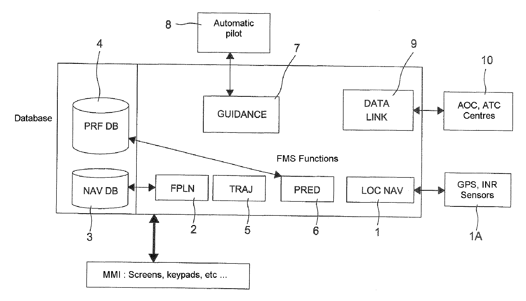
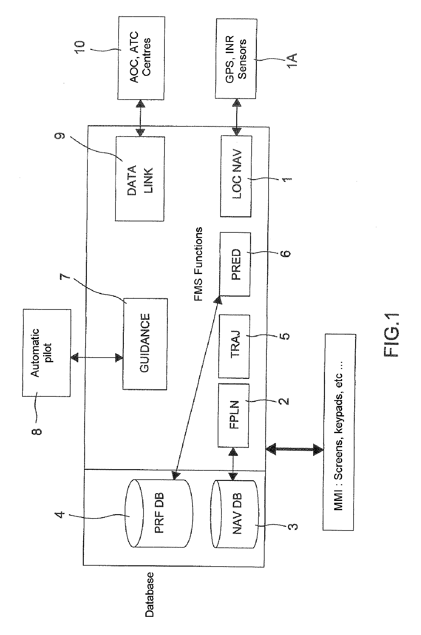
[0057]In the simplified block diagram of a conventional aircraft flight management device (termed FMS) of FIG. 1, which is furnished with a man-machine interface MMI, the following FMS functions, described in the ARINC 702 standard (Advanced Flight Management Computer System, Dec 1996), have been represented. They normally ensure all or some of the functions of:[0058]Navigation LOCNAV, referenced 1, to perform optimal location of the aircraft as a function of the geo-locating means (GPS, GALILEO, VHF radio beacons, inertial platforms, referenced 1A as a whole),[0059]Flight plan FPLN, referenced 2, to input the geographical elements constituting the skeleton of the route to be followed, namely: departu...


PUM


Abstract

The method in accordance with the invention is a method of providing a 3D emergency descent trajectory for aircraft comprising the steps of searching for at least one possible better trajectory allowing a secure continuation in relation to the relief and / or the surrounding conditions towards a homing point as soon as a situation requiring an unscheduled modification of the current trajectory occurs, wherein this trajectory is updated as a function of the alterations in the surrounding conditions, as a function of the information provided by the onboard sensors and / or outside information received.

Description

RELATED APPLICATIONS[0001]The present application is based on, and claims priority from, France Application Number 06 08870, filed Oct. 10, 2006, the disclosure of which is hereby incorporated by reference herein in its entirety.FIELD OF THE INVENTION[0002]The present invention pertains to a method of forming a 3D safe emergency descent trajectory for aircraft as well as to a device for implementing this method.BACKGROUND OF THE INVENTION[0003]Exceptional situations, in particular those requiring a safe descent in proximity to the relief, require fast decisions to be taken under conditions of extreme stress.[0004]The first few minutes after detecting an incident are critical and a bad decision can have serious consequences on the continuation of the flight or the workload imposed on the crew to deal with it or rectify it.[0005]The problems posed by an emergency descent have been mentioned for example in the following publications:[0006]the safety bulletin of the FAA, according to wh...

Claims


Application Information

Patent Timeline
Patent Type & Authority Applications(United States)
IPC IPC(8): G01C23/00G01S13/935
CPCG01C21/00G05D1/0676G08G5/0039
Inventor DEKER, GUYMARTY, NICOLASCOULMEAU, FRANCOIS
Owner THALES SA
Why Eureka
Try Eureka