Brake system

Inactive Publication Date: 2008-07-31
HONDA MOTOR CO LTD
View PDF8 Cites 35 Cited by
  • Summary
  • Abstract
  • Description
  • Claims
  • Application Information

AI Technical Summary

Benefits of technology

[0007]The present invention has been made in view of the above-described circumstances, and it is an object of the present invention to enhan

Problems solved by technology

However, if the rated rotational speed of the electric motor is set at a high value in order to enhance the response of braking force generation in an emergency situation, the rated torque decreases correspondingly, leading to a possibility that the torque of the electric

Method used


Image

  • Brake system
  • Brake system
  • Brake system

Examples


second embodiment

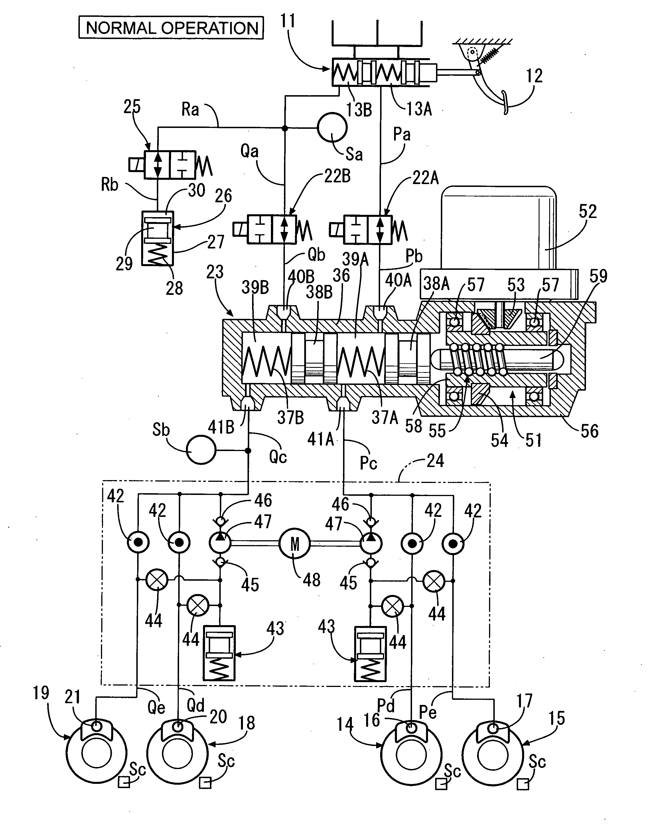
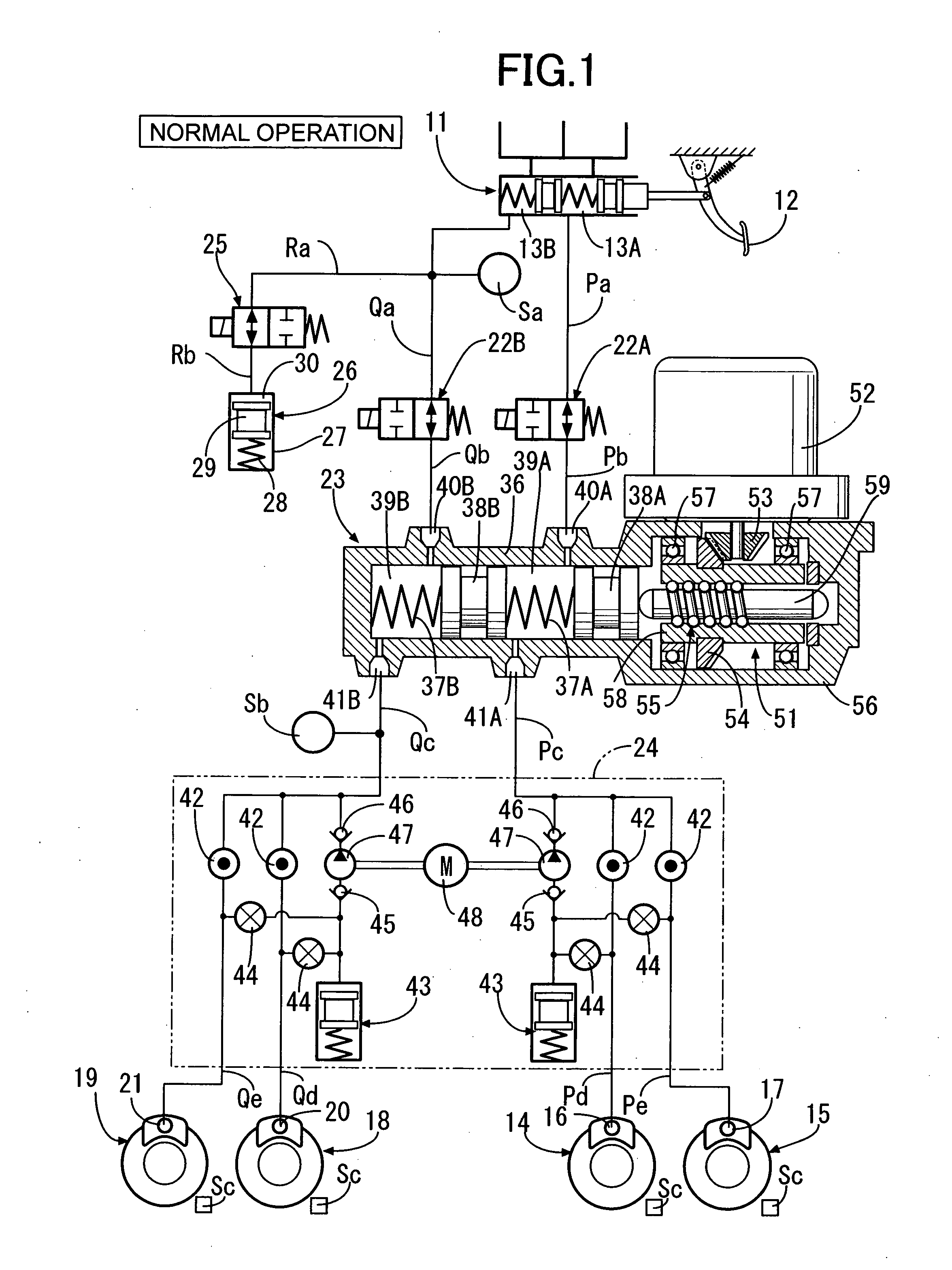
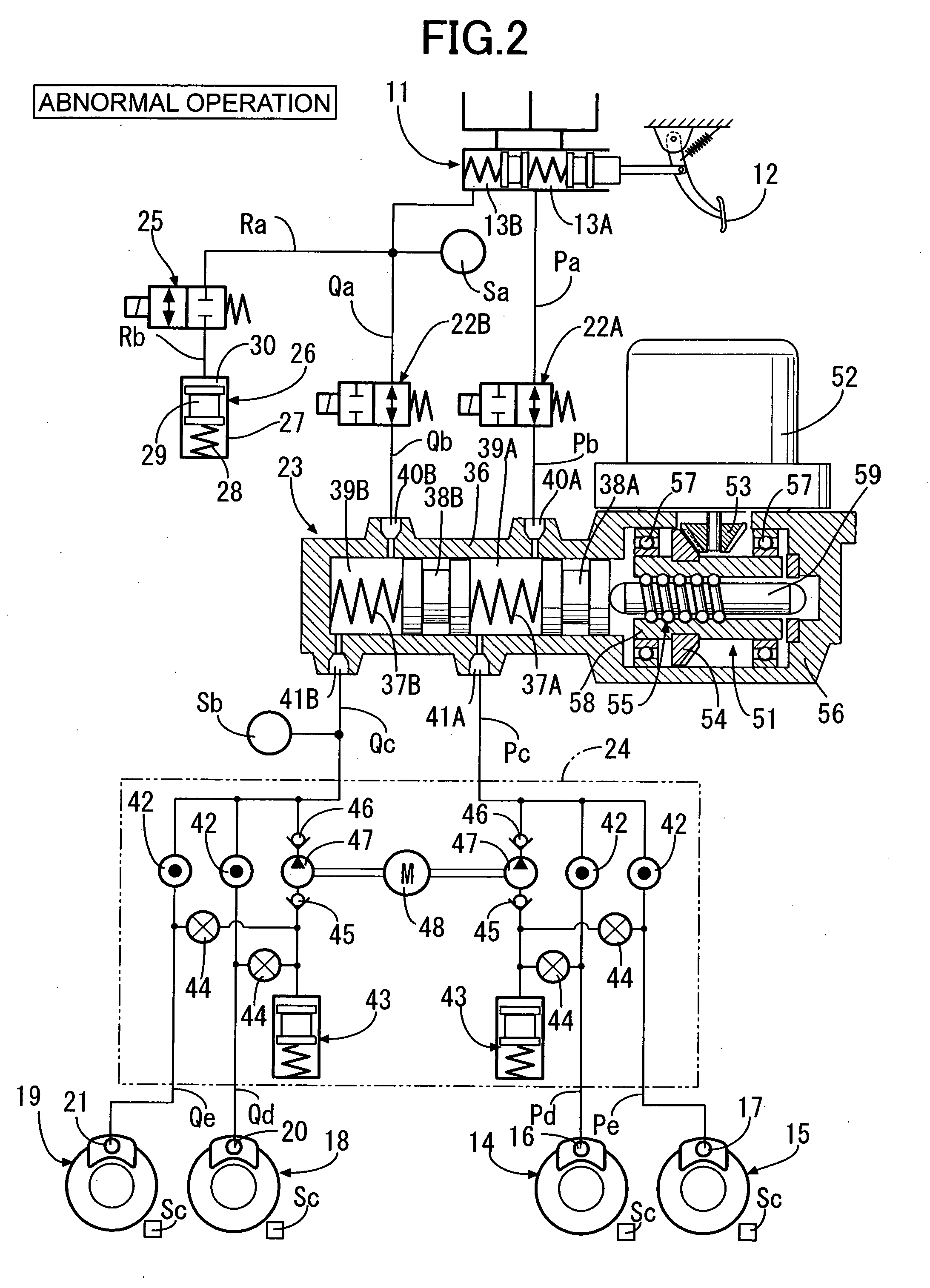
[0053]FIGS. 7A to 10 show the present invention.

[0054]In the first embodiment, the field-weakening operation of the electric motor 52 is performed in accordance with the target brake fluid pressure, whereas in the second embodiment, the field-weakening operation of the electric motor 52 is performed in accordance with the load characteristics of the slave cylinder 23 represented by caliper rigidity of the wheel cylinders 16, 17, 20, 21.

[0055]The calipers of the wheel cylinders 16, 17, 20, 21 generate a braking force by pressing the brake pad against the brake disc with the brake fluid pressure. In the case where the rigidity of the caliper main body supporting the brake pad decreases due to secular change or the brake pad itself wears, even if the brake fluid pressure is applied on the caliper, the contact face pressure between the brake pad and the brake disc does not quickly increase, leading to a problem of a lowered response of braking force generation.

[0056]When the driver appl...


PUM


Abstract

A brake system includes an electric brake force generator which brakes a wheel using a driving force of an electric motor and an electric motor controller that performs a field-weakening control of the electric motor. The electric motor controller performs the field-weakening control of the electric motor which then operates the electric brake force generator. Thus, the rotational speed of the electric motor is increased when the field weakening control is performed by the electric motor controller thereby quickly activating the electric braking force generator to enhance response of brake force generation.

Description

CROSS-REFERENCE TO RELATED APPLICATIONS[0001]The present invention claims priority under 35 USC §119 based on Japanese patent application No. 2007-19753 filed 30 Jan. 2007. The subject matter of this priority document is incorporated by reference herein.BACKGROUND OF THE INVENTION[0002]1. Field of the Invention[0003]The present invention relates to a brake system comprising an electric braking force generator that brakes a wheel by using a driving force of an electric motor.[0004]2. Description of the Related Art[0005]Japanese Patent Application Laid-open No. 2005-343366 discloses a brake system of the type referred to as a brake by wire (BBW) brake system, which converts a braking operation of a driver into an electrical signal used to operate a motor cylinder or slave cylinder as an electric braking force generator, and operates a wheel cylinder by brake fluid pressure generated by the motor cylinder.[0006]In an emergency situation such as collision avoidance, the rotational speed...

Claims


Application Information

Patent Timeline
IPC IPC(8): B60T13/00
CPCB60T8/3275B60T8/4081B60T2201/03B60T13/745B60T17/221B60T13/662
Inventor MATSUSHITA, SATOSHI
Owner HONDA MOTOR CO LTD
Why Eureka
Try Eureka