
Sound determination method and sound determination apparatus

Inactive Publication Date: 2008-07-31
FUJITSU LTD
View PDF7 Cites 46 Cited by
  • Summary
  • Abstract
  • Description
  • Claims
  • Application Information

AI Technical Summary

Benefits of technology

[0009]Taking the aforementioned problems into consideration, it is the main object of the present invention to provide: a sound determination method that is capable of easily identifying the occurrence interval of the sound coming from a target sound source even in a loud environment by calculating the phase difference spectrum of acoustic signals that are received by a plurality of microphones, and determining that the acoustic signal coming from the nearest sound source that is the target of identification is included when the calculated phase difference is equal to or less than a specified threshold value; and a sound determination apparatus which employs that sound determination method.
[0030]In the tenth aspect, when identifying an acoustic signal that is a voice, sound determination is performed after eliminating frequency bands that are equal to or less than a fundamental frequency at which the voice spectrum does not exist according to the frequency characteristics of a voice. This makes it possible to improve the accuracy of identifying the acoustic signal from the target sound source.

Problems solved by technology

However, in an environment in which there is an occurrence of noise such as ambient noise or non-stationary noise, the power distribution that is found through delay-sum processing (used for delay-sum beamforming) using the incident angle as a variable has a problem in that a plurality of peaks appear or the peaks become broad, so it becomes difficult to identify the nearby target sound source.
Also, when sound from the nearby target sound source is not emitted continuously at a constant intensity, the peak of the power distribution becomes dull due to the ambient noise, so there is a problem in that it becomes even more difficult to detect the time interval at which the sound coming from the target sound source is emitted.
Furthermore, in the method disclosed in U.S. Pat. No. 6,243,322, all frequency bands are used, including bands having a poor S / N ratio, so in a loud environment there is a problem in that the peak at the angle from which the sound from the nearby sound source comes becomes dull, and thus it is difficult to accurately determine the sound that comes from the nearby sound source.

Method used


Image

  • Sound determination method and sound determination apparatus
  • Sound determination method and sound determination apparatus
  • Sound determination method and sound determination apparatus

Examples


first embodiment

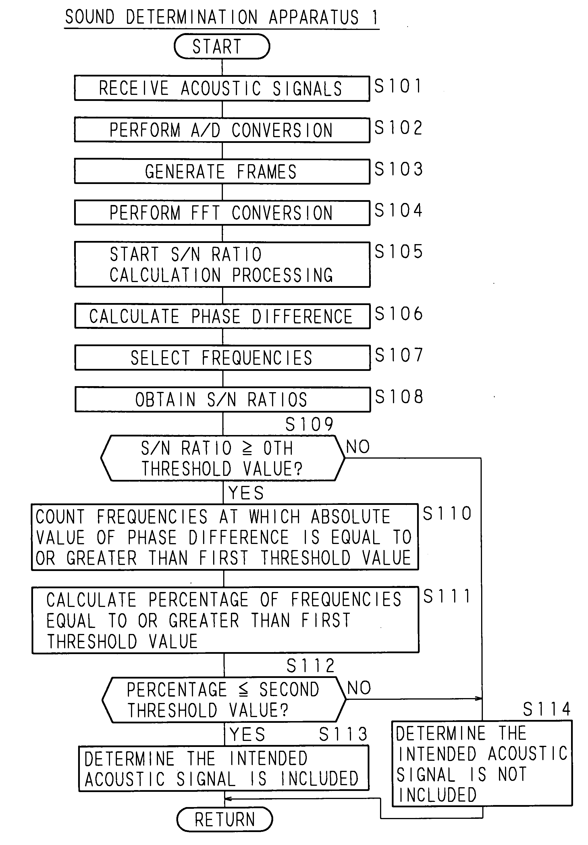
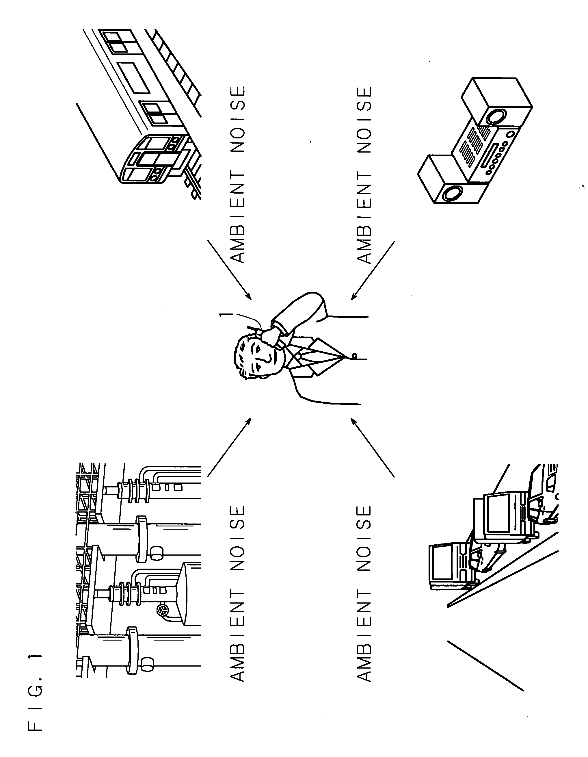
[0045]FIG. 1 is a drawing showing an example of the sound determination method of the first embodiment of the invention. In FIG. 1, the reference number 1 is a sound determination apparatus which is applied to a mobile telephone, and the sound determination apparatus 1 is carried by the user and receives the voice spoken by the user as an acoustic signal. Moreover, in addition to the voice of the user, the sound determination apparatus 1 receives various ambient noises such as voices of other people, machine noise, music and the like. Therefore, the sound determination apparatus 1 performs processing for suppressing noise by identifying the target acoustic signal from among the various acoustic signals that are received from a plurality of sound sources, then emphasizing the identified acoustic signal, and suppressing the other acoustic signals. The target acoustic signal of the sound determination apparatus 1 is the acoustic signal coming from the sound source that is nearest to th...

second embodiment

[0069]The second embodiment is a form that limits the intended acoustic signal coming from the sound source in the first embodiment to a human voice. The sound determination method, as well as the construction and function of the sound determination apparatus of the second embodiment are the same as those of the first embodiment, so an explanation of them can be found by referencing the first embodiment, and a detailed explanation of them is omitted here. In the explanation below, the same reference numbers are given to components that are the same as those of the first embodiment.

[0070]In the second embodiment, further selection conditions according to the voice characteristics are added to selection by the selection unit 114 in the sound determination process of the first embodiment. FIGS. 9A, 9B are graphs showing an example of the voice characteristics used in the sound determination method of the second embodiment. FIGS. 9A, 9B show the characteristics of a female voice, where ...

third embodiment

[0074]The third embodiment is a form in which the relative position of the sound receiving units in the first embodiment can be changed. The sound determination method, as well as the construction and function of the sound determination apparatus of the third embodiment are the same as those of the first embodiment, so an explanation of them can be found by referencing the first embodiment, and a detailed explanation of them is omitted here. However, the relative position of the respective sound receiving units can be changed such as in the case of external microphones that are connected to the sound determination apparatus by a wired connection, for example. In the explanation below, the same reference numbers are given to components that are the same as those of the first embodiment.

[0075]In the case of the acoustic velocity V (m / s), the distance (width) between sound receiving units 13, 13 W (m), and the sampling frequency F (Hz), it is preferred that the relationship between the...


PUM


Abstract

A sound determination apparatus receives acoustic signals by a plurality of sound receiving units, and generates frames having a predetermined time length. The sound determination apparatus performs FFT on the acoustic signals in frame units, and converts the acoustic signals to a phase spectrum and amplitude spectrum, which are signals on a frequency axis, then calculates the difference at each frequency between the respective acoustic signals as a phase difference, and selects frequencies to be the target of processing. The sound determination apparatus calculates the percentage of frequencies at which the absolute values of the phase differences of the selected frequencies are equal to or greater than a first threshold value, and determines that the acoustic signal coming from the nearest sound source is included in the frame when the calculated percentage is equal to or less than a second threshold value.

Description

CROSS-REFERENCE TO RELATED APPLICATION[0001]This Nonprovisional application claims priority under 35 U.S.C §119(a) on Patent Application No. 2007-19917 filed in Japan on Jan. 30, 2007, the entire contents of which are hereby incorporated by reference.BACKGROUND OF THE INVENTION[0002]This invention relates to a sound determination method and sound determination apparatus which, based on acoustic signals that are received from a plurality of sound sources by a plurality of sound receivers, determines whether or not there is a specified acoustic signal, and more particularly to a sound determination method and sound determination apparatus for identifying the acoustic signal from the nearest sound source from a sound receiver.[0003]With the current advancement of computer technology, it has become possible to execute processing at practical processing speed even for acoustic signal processing that requires a large quantity of operation processing. Because of this, it is anticipated tha...

Claims


Application Information

Patent Timeline
IPC IPC(8): G01S3/808G10L21/028G10L21/0308G10L25/18G10L25/78G10L25/84G10L25/90
CPCG10L21/0208G10L25/27G10L2021/02166G10L25/78G10L25/48
Inventor HAYAKAWA, SHOJI
Owner FUJITSU LTD
Learn More