
Receiver, wireless device and method for cancelling a DC offset component

a technology of dc offset and receiver, applied in the field of receiving techniques in wireless communication, can solve the problems of deteriorating the performance of receiving signals and insufficient signal amplification

Inactive Publication Date: 2008-07-31
KK TOSHIBA
View PDF4 Cites 9 Cited by
  • Summary
  • Abstract
  • Description
  • Claims
  • Application Information

AI Technical Summary

Benefits of technology

[0009]It is an object of the present invention, in view of the above conventional problems, to provide a receiver which can remove a DC offset component from a signal to be received even under the condition of the amplification of the signal, a wireless device using the receiver and the corresponding method of cancelling a DC offset component.
[0013]According to the aspects of the invention can be removed the DC offset component effectively and efficiently from the corresponding signal even under the condition of the amplification of the signal.

Problems solved by technology

If a signal containing the DC offset component is amplified at the amplifier, the amplification of the signal is saturated due to the DC offset component so that the signal can not be amplified sufficiently.
As a result, the receiving performance of the signal may be deteriorated remarkably at the corresponding receiver.

Method used


Image

  • Receiver, wireless device and method for cancelling a DC offset component
  • Receiver, wireless device and method for cancelling a DC offset component
  • Receiver, wireless device and method for cancelling a DC offset component

Examples


Embodiment Construction

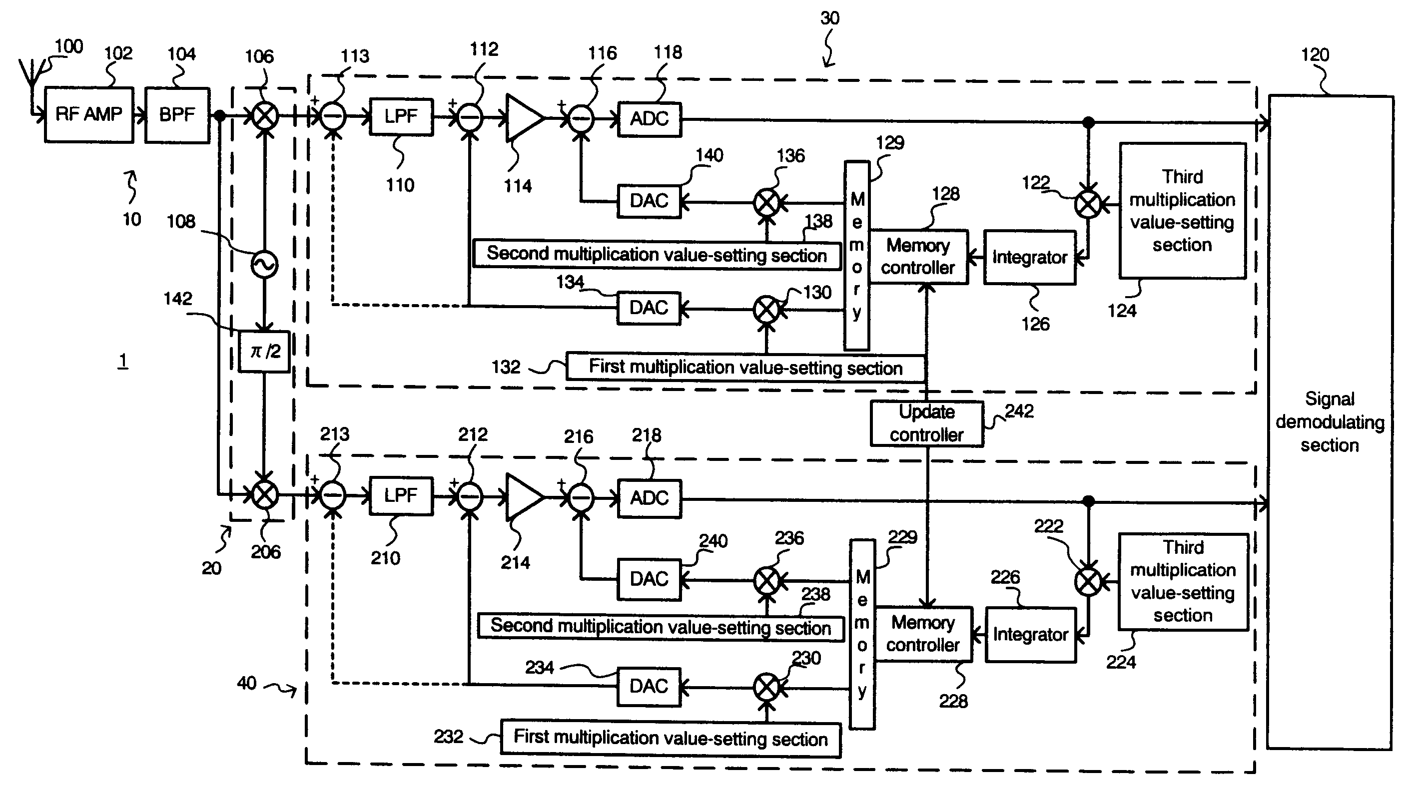
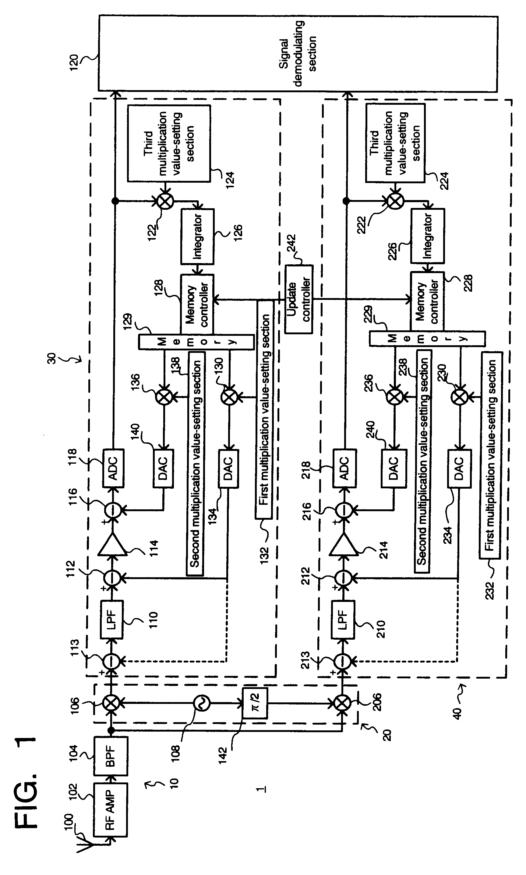
[0025]The embodiments will be described with reference to drawings. FIG. 1 is a block diagram relating to the structure of the receiver according to a first embodiment. As illustrated in FIG. 1, the receiver 1 in this embodiment includes an RF unit 10, a frequency converting unit 20, an I channel processing unit 30, a Q channel processing unit 40 and a signal demodulating unit 120.

[0026]The RF unit 10 includes an antenna 100, a high frequency amplifier (RF amplifier) 102 and a bandpass filter (BPF) 104 so as to receive a high frequency radio wave and output the corresponding received signal. The radio wave is mainly received by the antenna 100, and amplified to a desired gain level by the RF amplifier 102. In this case, unnecessary frequency components in the signal are removed by the BPF 104 so that the intended frequency component(s) can be extracted from the signal.

[0027]The frequency converting unit 20 includes a first mixer 106, a second mixer 206, a local oscillator 108 and a ...


PUM


Abstract

A receiver includes a memory for storing DC offset amounts in accordance with a DC offset component remaining in a received signal; a first DC offset component-removing unit configured so as to generate a first DC offset amount from the DC offset amounts stored in the memory and to remove the first DC offset amount from the received signal; an amplifier for amplifying a signal output from the first DC offset component-removing unit; and a second DC offset component-removing unit configured so as to generate a second DC offset amount from the DC offset amounts stored in the memory in view of a gain of the amplifier and remove the second DC offset amount from the signal amplified by the amplifier.

Description

CROSS-REFERENCE TO RELATED APPLICATIONS[0001]This application is based upon and claims the benefit of priority from the prior Japanese Patent Application No. 2007-16289, filed on Jan. 26, 2007; the entire contents of which are incorporated herein by reference.BACKGROUND OF THE INVENTION[0002]1. Field of the Invention[0003]The present invention relates to receiving technique in wireless communication, particularly, to a receiver to remove a DC offset component remaining in a received signal, a wireless device using the receiver and a method for cancelling a DC offset component.[0004]2. Description of the Related Art[0005]With a wireless device such as a receiver to be employed in wireless communication, a direct conversion system to directly convert the frequency of a signal received is widely available. With the direct conversion system, since the received signal is multiplied by a local signal to gain an intended baseband signal, a DC offset component may be generated originated fr...

Claims


Application Information

Patent Timeline
IPC IPC(8): H04L25/10H03K5/007
CPCH03M1/1019H04L25/06H03M1/12
Inventor OKUNI, HIDENORIITO, RUIYOSHIDA, HIROSHI
Owner KK TOSHIBA
Learn More