Pump and pump control circuit apparatus and method

a control circuit and pump control technology, applied in the direction of pump control, motor parameters, positive displacement liquid engine, etc., to achieve the effect of reducing diaphragm stress, reducing diaphragm stress, and prolonging diaphragm li

Inactive Publication Date: 2008-07-31
SHURFLO
View PDF65 Cites 88 Cited by
  • Summary
  • Abstract
  • Description
  • Claims
  • Application Information

AI Technical Summary

Benefits of technology

[0009]Some embodiments of the present invention provide a diaphragm for use with a pump having pistons driving the diaphragm to pump fluid through the pump. The pistons can be integrally formed in a body portion of the diaphragm, thereby resulting in fewer components for the manufacture and assembly of the pump. Also, each of the pistons can be coupled (i.e., attached to or integral therewith) to the body portion of the diaphragm by a convolute. Each of the pistons can have a top surface lying generally in a single plane. In some embodiments, each convolute is comprised of more material at its outer perimeter so that the bottom surface of each convolute lies at an angle with respect to the plane of the piston top surfaces. The angled bottom surface of the convolutes allows the pistons a greater range of motion with respect to the outer perimeter of the convolute, and can reduce diaphragm stresses for longer diaphragm life.
[0010]In some embodiments of the present invention, an outlet port of the pump is positioned tangentially with respect to the perimeter of an outlet chamber. The tangential outlet port allows fluid flowing in a circular path within the outlet chamber to continue along the circular path as the fluid exits the outlet chamber. This results in better pump efficiency, especially at lower pressures and higher flow rates.
[0011]Some embodiments of the present invention further provide a pump having a non-mechanical pressure sensor coupled to a pump control system. However, some embodiments of the pump do not include a pressure sensor or a pump control system. The pressure sensor provides a signal representative of the changes in pressure within the pump to a microcontroller within the pump control system. Based upon the sensed pressure, the microcontroller can provide a pulse-width modulation control signal to an output power stage coupled to the pump. The output power stage selectively provides power to the pump based upon the control signal. Due to the pulse-width modulation control signal, the speed of the pump gradually increases or decreases rather than cycling between completely “on” and completely “off,” resulting in more efficient and quieter operation of the pump.
[0012]The pump control system can also include an input power stage designed to be coupled to a battery. The microcontroller is coupled to the input power stage in order to sense the voltage level of the battery. If the battery voltage is above a high threshold (e.g., when the battery is being charged), the microcontroller can prevent power from being provided to the pump. If the battery voltage is below a low threshold (e.g., when the voltage available from the battery will only allow the pump to stall below the shut-off pressure), the microcontroller can also prevent power from being provided to the pump. In some embodiments, the microprocessor only generates a control signal if the sensed battery voltage is less than the high threshold and greater than the low threshold.
[0014]In some embodiments, the pump control system limits the current provided to the pump in order to prevent high currents from damaging the pump's components. The pump control system is capable of adjusting a current limit value based upon the sensed pressure of the fluid within the pump. The pump control system can include a current-sensing circuit capable of sensing the current being provided to the pump. If the sensed current is less than the current limit value, the microcontroller can generate a high control signal so that the output power stage provides power to the pump. If the sensed current is greater than the current limit value, the microcontroller can generate a low control signal until the sensed current is less than the current limit value.
[0017]If the sensed pressure is less than the shut-off pressure value and the pump is turned off, the microprocessor can generate a pulse-width modulation control signal to re-start the pump. The microcontroller can sense the pressure of the fluid within the pump and adjust the current limit value based on the sensed pressure. The microcontroller can also sense the current being provided to the pump. If the sensed current is greater than the current limit value, the microcontroller can adjust the pulse-width modulation control signal in order to provide less power to the pump. If the sensed current is less than the current limit value, the microcontroller can adjust the pulse-width modulation control signal in order to provide more power to the pump.

Problems solved by technology

However, some embodiments of the pump do not include a pressure sensor or a pump control system.

Method used


Image

  • Pump and pump control circuit apparatus and method
  • Pump and pump control circuit apparatus and method
  • Pump and pump control circuit apparatus and method

Examples


Embodiment Construction

[0059]Before one embodiment of the invention is explained in full detail, it is to be understood that the invention is not limited in its application to the details of construction and the arrangement of components set forth in the following description or illustrated in the following drawings. The invention is capable of other embodiments and of being practiced or of being carried out in various ways. Also, it is to be understood that the phraseology and terminology used herein is for the purpose of description and should not be regarded as limiting. The use of “including” and “comprising” and variations thereof herein is meant to encompass the items listed thereafter and equivalents thereof as well as additional items.

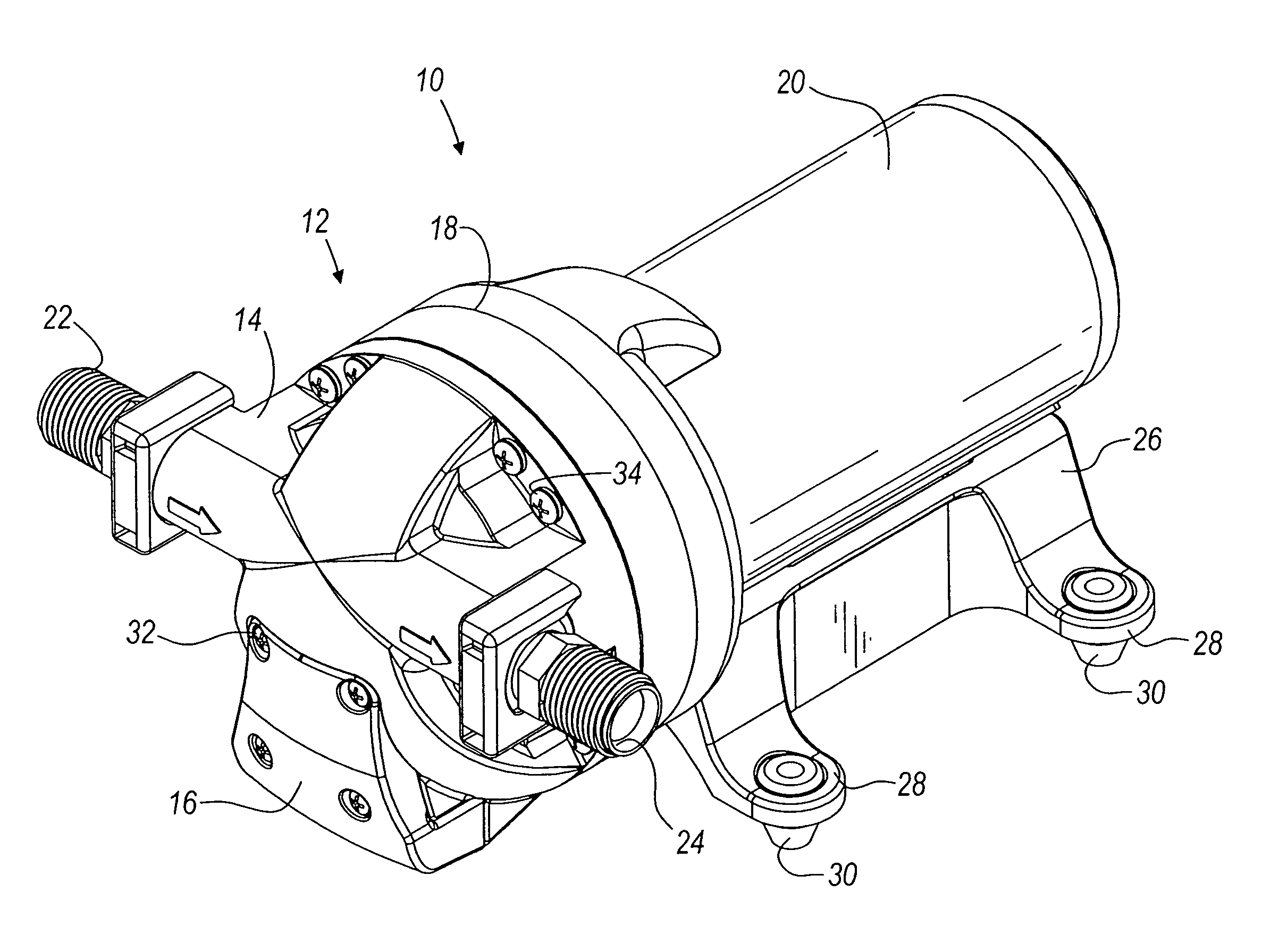
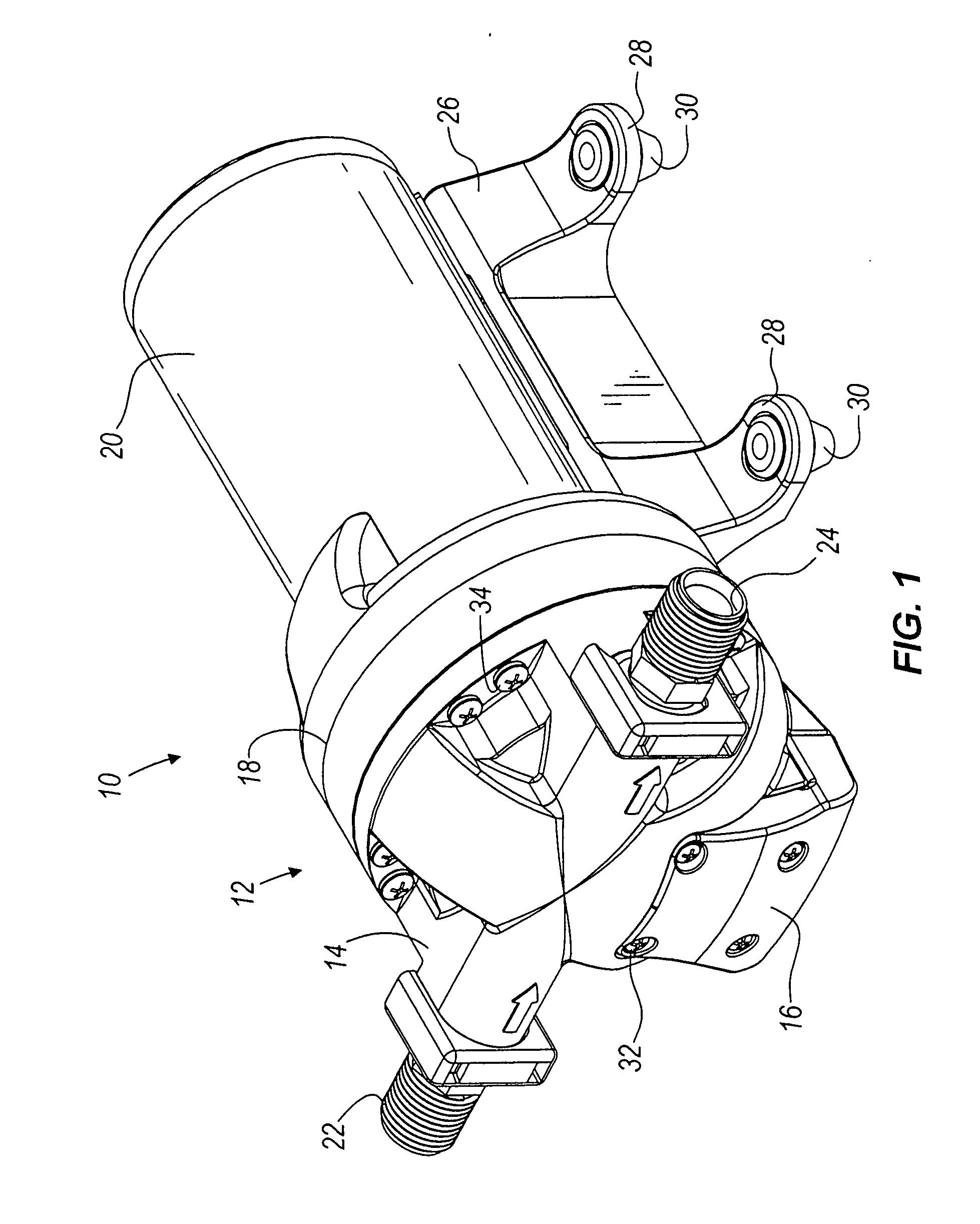
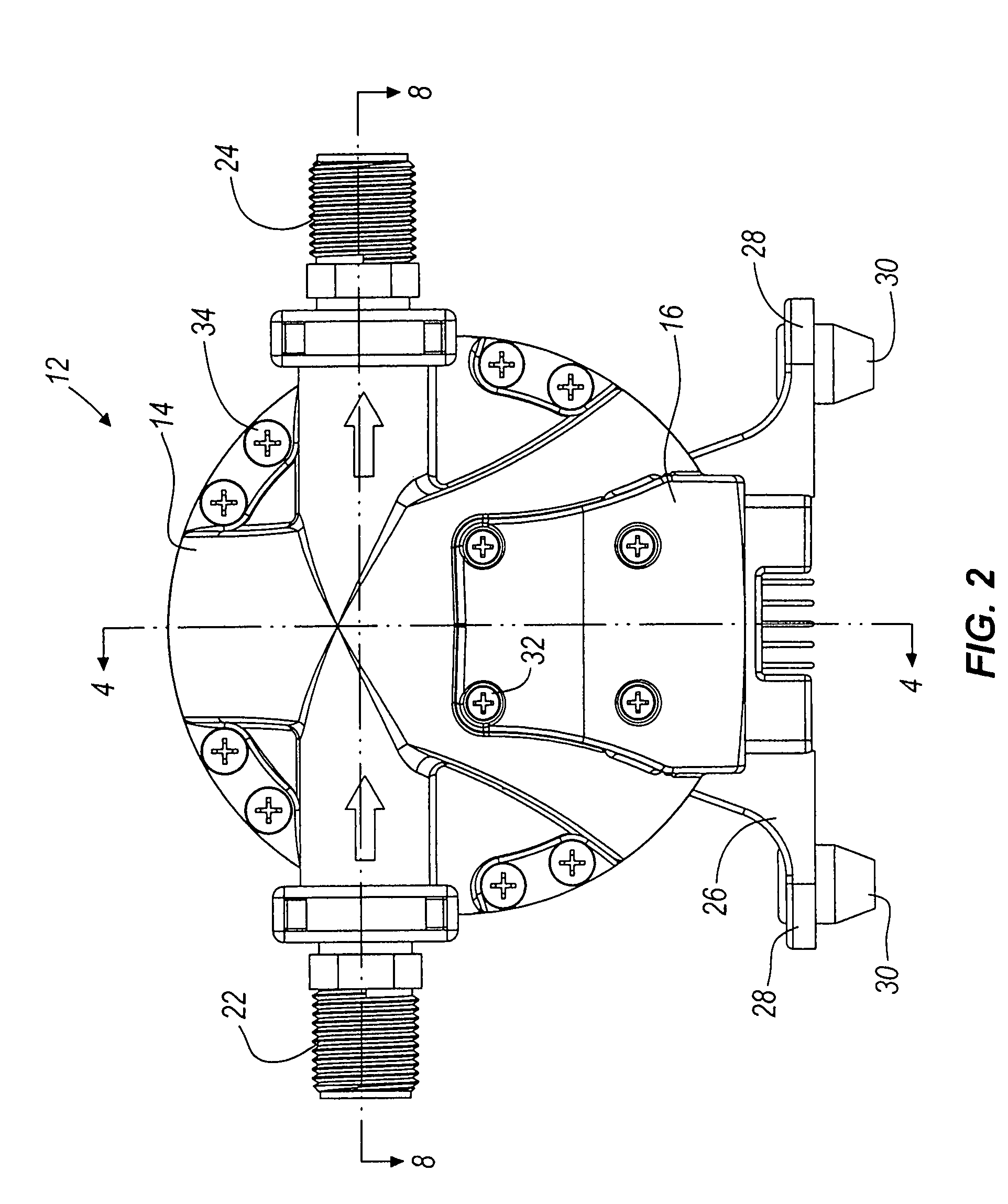
[0060]FIGS. 1-3 illustrate the exterior of a pump 10 according to one embodiment of the present invention. In some embodiments such as that shown in the figures, the pump 10 includes a pump head assembly 12 having a front housing 14, a sensor housing 16 coupled to th...


PUM


Abstract

A method and apparatus for a pump and a pump control system. The apparatus includes pistons integrally formed in a diaphragm and coupled to the diaphragm by convolutes. The convolutes have a bottom surface angled with respect to a top surface of the pistons. The apparatus also includes an outlet port positioned tangentially with respect to the perimeter of an outlet chamber. The apparatus further includes a non-mechanical pressure sensor and a temperature sensor coupled to a pump control system. For the method of the invention, the microcontroller provides a pulse-width modulation control signal to an output power stage in order to selectively control the power provided to the pump. The control signal is based on the pressure within the pump, the current being provided to the pump, the voltage level of the battery, and the temperature of the pump.

Description

RELATED APPLICATIONS[0001]This application is a divisional of pending U.S. application Ser. No. 11 / 355,662, filed on Feb. 16, 2006; which is a continuation-in-part of U.S. application Ser. No. 10 / 453,874 filed on Jun. 3, 2003, which issued as U.S. Pat. No. 7,083,392; which is a continuation-in-part of U.S. application Ser. No. 09 / 994,378 filed on Nov. 26, 2001, which issued as U.S. Pat. No. 6,623,245, all of which are incorporated herein by reference.FIELD OF THE INVENTION[0002]This invention relates generally to pumps and pumping methods, and more particularly to wobble plate pumps and pump controls.BACKGROUND OF THE INVENTION[0003]Wobble-plate pumps are employed in a number of different applications and operate under well-known principals. In general, wobble-plate pumps typically include pistons that move in a reciprocating manner within corresponding pump chambers. In many cases, the pistons are moved by a cam surface of a wobble plate that is rotated by a motor or other driving ...

Claims


Application Information

Patent Timeline
Patent Type & Authority Applications(United States)
IPC IPC(8): F04B49/10F04B43/00F04B43/02F04B43/04F04B49/06
CPCF04B43/0054F04B43/0081F04B43/026F04B2205/04F04B49/065F04B2203/0201F04B2203/0208F04B43/04
Inventor MEZA, HUMBERTO V.GANDHI, NIKHIL JITENDRATROUNG, QUANG MINH
Owner SHURFLO
Why Eureka
Try Eureka