
Ultraviolet lamp for use in water purifiers

a technology of ultraviolet lamps and water purifiers, which is applied in the direction of water/sludge/sewage treatment, coupling device connections, chemical instruments and processes, etc., can solve the problems of preventing the insertion of the lamp into the socket, the contact pins are difficult to align to make the electrical connection necessary to operate the lamp, and the lamp's end cap is unintentionally separated from the socket, so as to improve the configuration of the lamp, and reduce the chance of connecting chan

Active Publication Date: 2008-07-31
LIGHT SOURCES INC
View PDF39 Cites 9 Cited by
  • Summary
  • Abstract
  • Description
  • Claims
  • Application Information

AI Technical Summary

Benefits of technology

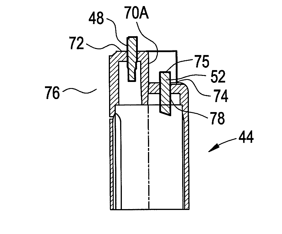
[0020]The utilization of one at least one female terminal pin located on the lamp base leads to improved lamp configurations in that polarization between the pairs of pins are more easily ensured; and the mating of the end cap and receptacle may be stronger. The designs will further allow for matching of the lamp and connector to a specific power supply to reduce the chance of connecting an ultraviolet lamp into an improperly matched power supply.

Problems solved by technology

This may be particularly important in certain applications where vibration or movement of the lamp or lamp fixture could result in unintentional separation between the lamp's end cap and the socket.
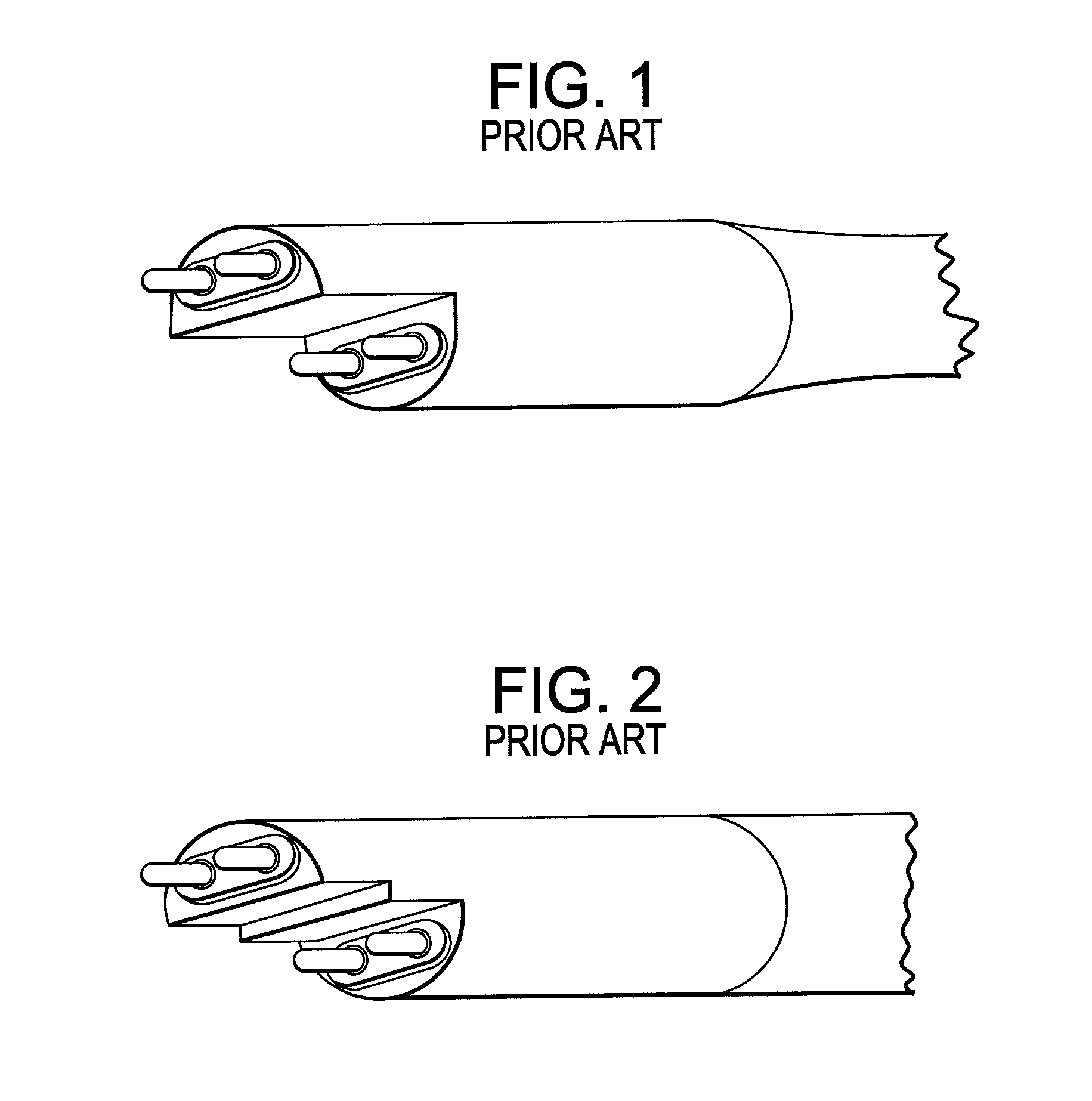
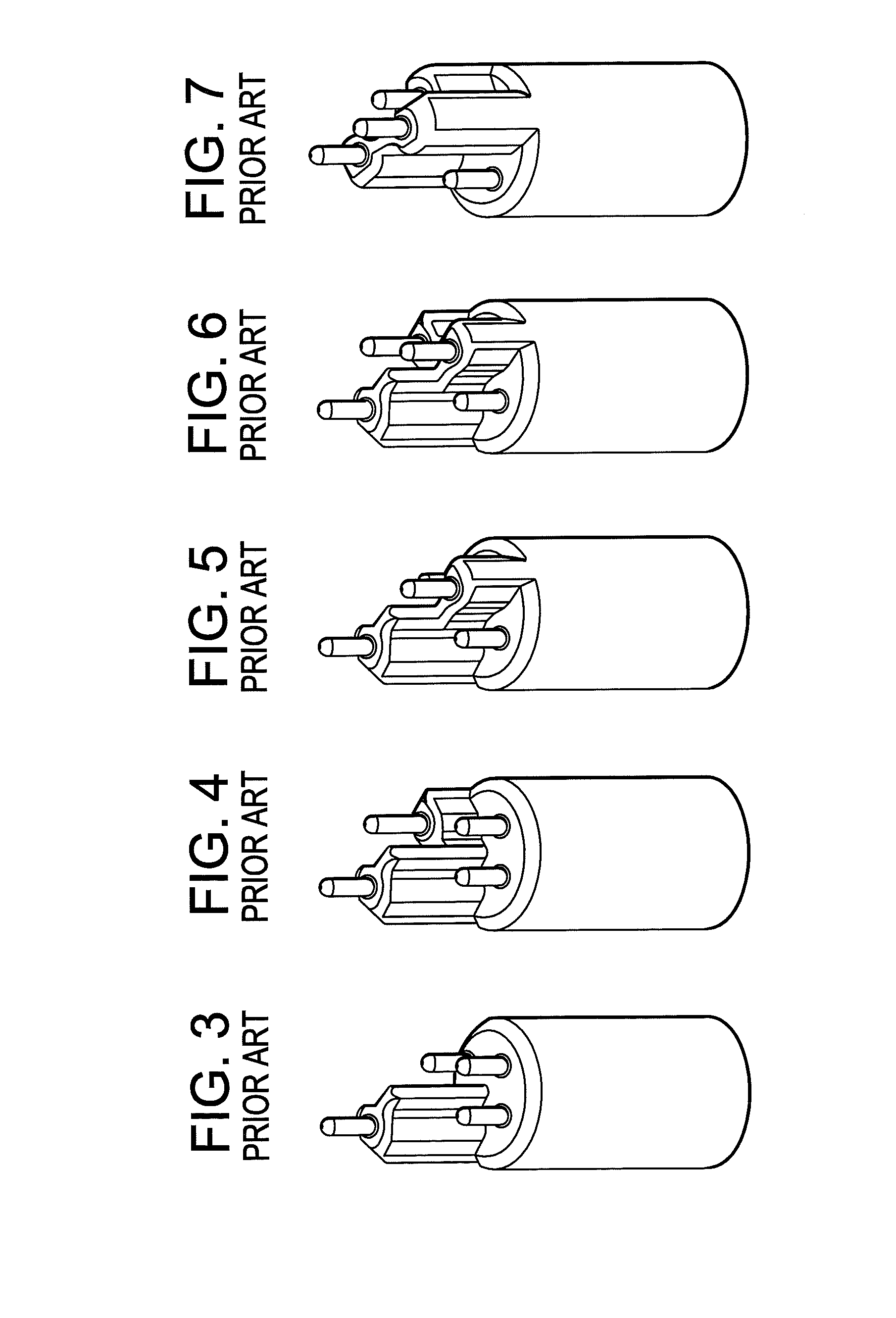
In some applications where a multiplicity of contact pins and / or pin orientations is utilized, it is often difficult to align the contact pins to make the electrical connection necessary to operate the lamp.
Often, the contact pins may become misaligned or bent due to their extension or projection from the base of the lamp, preventing their insertion into a socket.
It may also be possible to insert the end cap into a socket such that the contacts are not connected with the proper terminals in the socket, resulting in improper operation of the lamp.
Also, on a typical “slide into place” male / female pin connector there is no locking or twist locking and thus the pins may slide out and become disconnected easily by vibration for example.
As noted in WO / 2006 / 136026 to Elku et al. which is a variation of the slide-on pin connector above, a potential problem with this approach is that in many applications, the radiation lamp is immersed in a flow of water and turbulence created within that water treatment system invariably imparts a vibratory motion to the lamps.
This frequently results in the lamp being vibrated or shaken loose of its electrical connection base or socket thereby causing the lamp to be rendered completely or intermittently inoperative.
When such an event occurs, the water being treated may not be fully disinfected.
The potential problem with these approaches is the complexity of the mechanical connection between the lamp and the base unit requiring the use of springs, specialized connection lugs and the like.
Further, a connection system which is predicated on a dual motion system such that pushing and twisting if used incorrectly for example may give rise to higher incidents of lamp breakage, electrical shock, and other damage to the lamp by field personal.

Method used


Image

  • Ultraviolet lamp for use in water purifiers
  • Ultraviolet lamp for use in water purifiers
  • Ultraviolet lamp for use in water purifiers

Examples


Embodiment Construction

[0060]Referring now to FIG. 8 of the drawings, reference numeral 10 generally identifies a water purifier having a cylindrical housing 12 extending along a longitudinal axis. A hollow, axially-extending sleeve 14 is centrally mounted within the housing 12 between apertured support walls 18, 20 spaced apart along the longitudinal axis. The support walls 18, 20, together with the interior wall of the housing 12 and the exterior wall of the sleeve 14, bound an interior space 16. A water inlet 22 admits pressurized water to be purified into the space 16. A water outlet 24 discharges the purified water from the space 16. The space 16 serves as a flow-through passage for the water contained therein which, during the course of its flow, is exposed to ultraviolet radiation as described below.

[0061]A removable cover 26 overlies the support wall 18 at one end of the housing 12. The cover 26 is detachably coupled to the housing 12 by a set of threaded fasteners 28 to permit access to the inter...


PUM


Abstract

A lamp base is provided having terminal pins mounted on and extending outwardly along a longitudinal axis of the lamp base. At least one of the pins may be a female pin connector. The female pin connector may be provided within a sheath that extends from an end of the lamp base along a longitudinal axis of the lamp base.

Description

CROSS REFERENCE TO RELATED APPLICATIONS[0001]This application is a continuation in part (CIP) of U.S. application Ser. No. 11 / 870,256, filed Oct. 10, 2007, the contents of which are herein incorporated by reference and priority to which is hereby claimed. The 11 / 870,256 application is a continuation in part (CIP) of U.S. application Ser. No. 11 / 675,315, filed Feb. 15, 2007 which claimed the benefit of the date of earlier filed provisional application, U.S. Provisional Application No. 60 / 777,213, filed on Feb. 27, 2006, the contents of both of which are incorporated by reference herein, and priority to both which is hereby claimed.BACKGROUND OF THE INVENTION[0002]1. Field of the Invention[0003]This invention generally relates to improvements in lamps, especially ultraviolet lamps used in air and water purifiers.[0004]2. Description of Related Art[0005]Ultraviolet air and water or other liquid purifiers are known for disinfecting contaminated air or water or other liquid for domestic ...

Claims


Application Information

Patent Timeline
Patent Type & Authority Applications(United States)
IPC IPC(8): H01J5/54
CPCC02F1/325H01R33/965H01R13/53C02F2201/004
Inventor ZAYAS, BETTY JEAN
Owner LIGHT SOURCES INC
Learn More