Methods and Apparatus for Selectively Shunting Energy in an Implantable Extra-Cardiac Defibrillation Device

a technology of selective shunting and implantable extracardiac defibrillation, which is applied in the direction of internal electrodes, subcutaneous electrodes, therapy, etc., can solve the problems of more harm than good and render the eid inoperabl

Inactive Publication Date: 2008-07-31
MEDTRONIC INC
View PDF15 Cites 55 Cited by
  • Summary
  • Abstract
  • Description
  • Claims
  • Application Information

AI Technical Summary

Benefits of technology

[0012]In one embodiment, the EID electrically couples to one or more elongated, coil-type high voltage electrodes with the electrodes disposed in a location providing defibrillation vectors covering adequate mass of myocardial tissue to achieve defibrillation and deliver pacing therapy. Specifically, leads may be substantially implanted adjacent a portion of the external abdominal oblique; adjacent the cardiac no...

Problems solved by technology

The inventors suggest that for a number of reasons such therapy could cause more harm than good unless preventative measures are incorporated into the EID.
Due to the orientation of the electrodes upo...

Method used


Image

  • Methods and Apparatus for Selectively Shunting Energy in an Implantable Extra-Cardiac Defibrillation Device
  • Methods and Apparatus for Selectively Shunting Energy in an Implantable Extra-Cardiac Defibrillation Device
  • Methods and Apparatus for Selectively Shunting Energy in an Implantable Extra-Cardiac Defibrillation Device

Examples


first embodiment

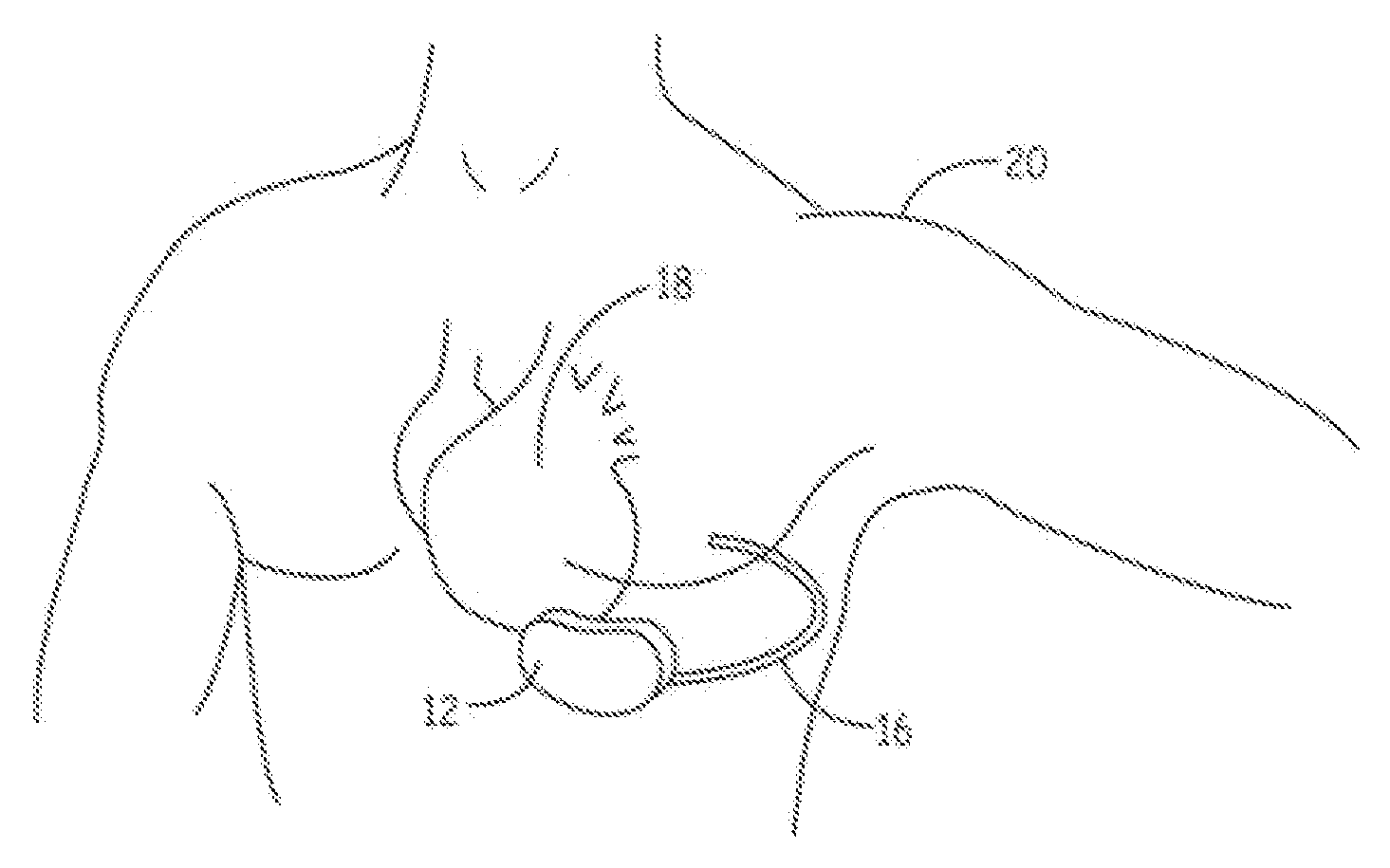
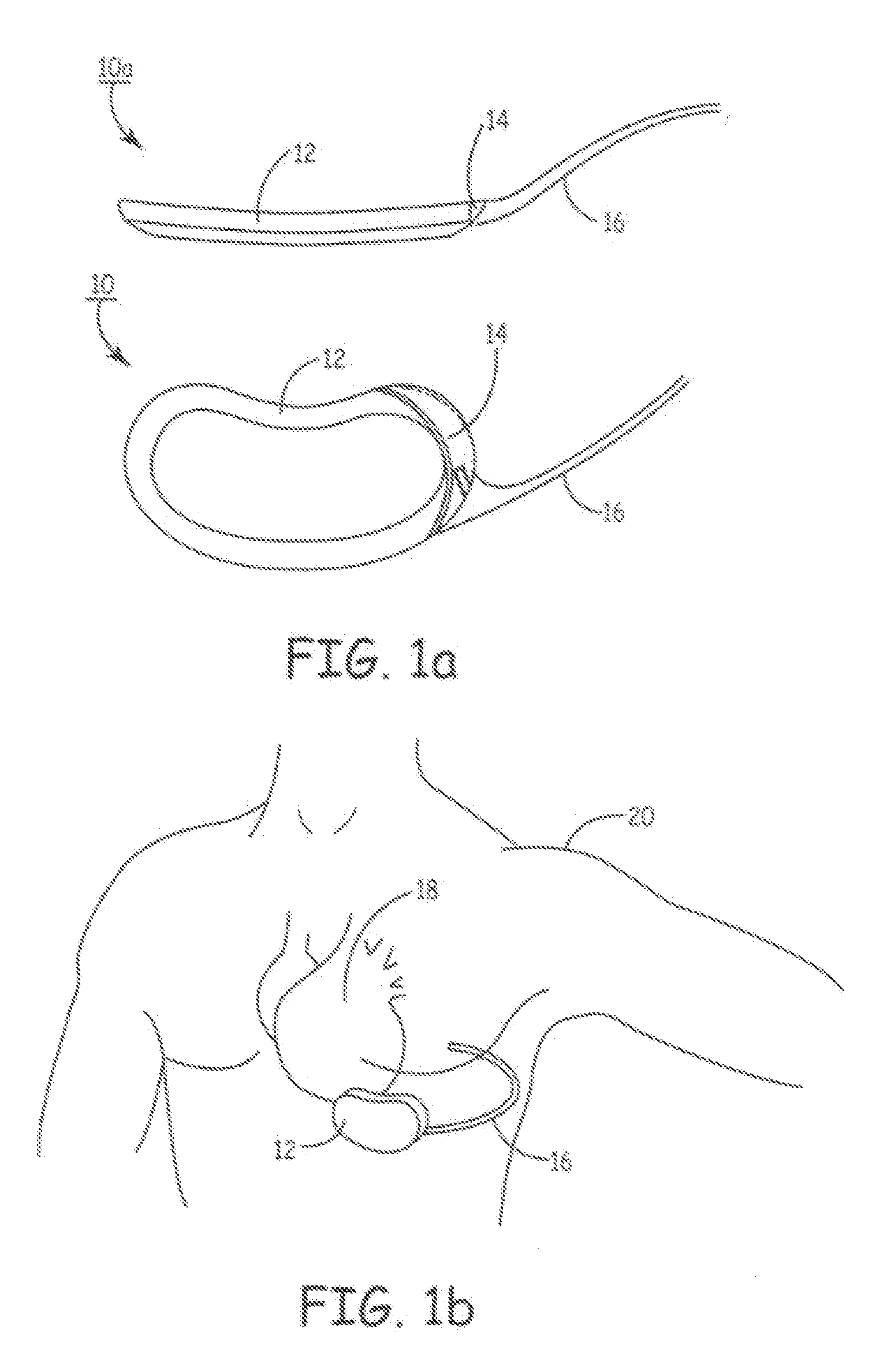
[0031]FIG. 1A depicts a multi-planar view of the present invention. EID 12 is an ovoid, substantially, kidney-shaped housing with connector 14 for attaching a subcutaneous sensing and cardioversion / defibrillation therapy delivery lead 16. EID 12 may be constructed of stainless steel, titanium or ceramic as described in U.S. Pat. No. 4,180,078 “Lead Connector for a Body Implantable Stimulator” to Anderson and U.S. Pat. No. 5,470,345 “Implantable Medical Device with Multi-layered Ceramic Enclosure” to Hassler, et al. The electronics circuitry of EID 10 (described herein pertaining to FIG. 21) may be incorporated on a polyamide flex circuit, printed circuit board (PCB) or ceramic substrate with integrated circuits packaged in leadless chip carriers and / or chip scale packaging (CSP). In one of the views, the concave construction of EID 12 is illustrated. The minor concavity of the housing of EID 12 follows the natural curve of the patient's median ribcage at about the cardiac notch. The...

second embodiment

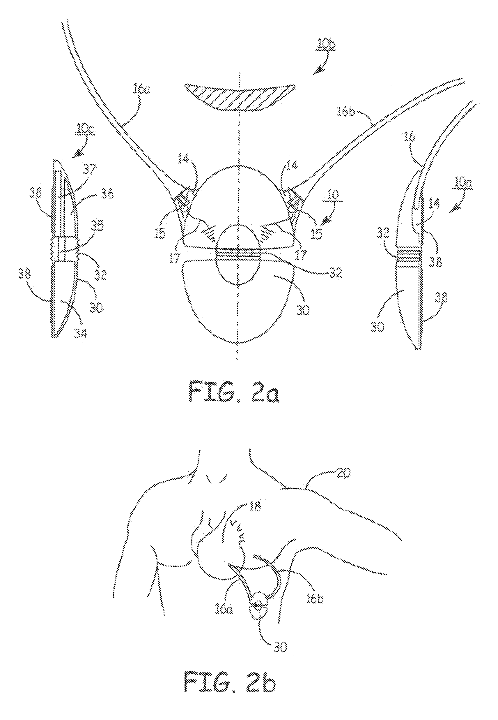
[0034]FIG. 2A is a multi-planar view of EID 30, the present invention. EID 30 is a convex, flexible ovaloid-shaped housing with connectors 14 (two shown) for attaching a pair of subcutaneous sensing and cardioversion / defibrillation therapy delivery leads 16A and 16b. According to the invention one or more components capable of limiting electrical voltage, such as a metal oxide varistor 15 couples to the leads 16a and 16b and via a conductor 17 to a source of common electrical reference voltage (e.g., the housing of EID 30).

[0035]EID 30 may be constructed of stainless steel, titanium or ceramic. View 10A is a side view of EID 30 showing the tapered housing 30, a mid-line flexible joint 32, connector 14, lead 16 and active can electrode 38. The active can electrode 38 allows sensing and cardioversion, defibrillation and / or pacing therapy delivery between the EID 30 and one or both leads 16A or 16b. The jointed housing 30 allows physician flexibility in selecting implant locations and ...

third embodiment

[0037]FIG. 3A is a multi-planar view of EID 40. EID 40 is an elongated slender ellipsoid with sections of partially articulating dynamic segments having surface mounted subcutaneous sensing and cardioversion / defibrillation therapy delivery electrodes 44 and 46. EID 40 may be constructed of stainless steel, titanium or ceramic or equivalent. View 10A is a top view of EID 40 showing the segmented construction (at 42). One or more of the segmented portions 45 can be adapted to house, for instance, high voltage defibrillation circuitry 47. According to the invention, an energy limiting component (or components) 43 can couple to an electrical reference (e.g., a ground or common electrical potential for the device, such as a portion of the metallic housing) and to a conductor 49 that couples to a high voltage electrode 44 (at 44′). Electrodes 44 and 46 located at opposite ends of EID 40 are typically 100 mm2 to 1000 mm2. View 10b is a further top view showing the dynamic flexibility of EI...


PUM


Abstract

The disclosure provides methods and apparatus for simultaneously providing protection to an implantable medical device, such as an extra-cardiac implantable defibrillator (EID), while allowing efficacious therapy delivery via an external defibrillator (e.g., an automated external defibrillator, or AED). Due to the orientation of the electrodes upon application of therapy via, for example, via an AED the structure of the EID essentially blocks therapy delivery. In addition, but for the teaching of this disclosure sensitive circuitry of an EID can be damaged during application of external high voltage therapy thus rendering the EID inoperable. EIDs are disclosed that are entirely implantable subcutaneously with minimal surgical intrusion into the body of the patient and provide distributed cardioversion-defibrillation sense and stimulation electrodes for delivery of cardioversion-defibrillation shock and pacing therapies across the heart when necessary. Configurations include one hermetically sealed housing with one or, optionally, two subcutaneous sensing and cardioversion-defibrillation therapy delivery leads or alternatively, two hermetically sealed housings interconnected by a power/signal cable. The housings are generally dynamically configurable to adjust to varying rib structure and associated articulation of the thoracic cavity and muscles. Further the housings may optionally be flexibly adjusted for ease of implant and patient comfort. One aspect includes partially insulating a surface of an EID that faces away from a heart while maintaining a major conductive surface facing the heart.

Description

FIELD OF THE INVENTION[0001]The present invention relates to the field of chronically implantable medical devices; in particular, the invention relates to methods and apparatus to selectively shunt externally-delivered defibrillation energy delivered to a subject who has an extra-cardiac implantable defibrillator (EID) to preserve the EID and to allow the externally-delivered defibrillation waveform and its accompanying therapeutic energy to reach the myocardium.BACKGROUND OF THE INVENTION[0002]Both automated external defibrillators (AEDs) and implantable cardioverter-defibrillators (ICDs) are becoming increasing available and it is estimated that as a result many thousands of individuals have received life-saving defibrillation therapy.[0003]More recently non-transvenous, extra-cardiac ICDs—herein EIDs (whether or not such devices include cardioversion capability)—have begun to be developed and might become as widespread as ICDs are today. As a result, the possibility exists that a...

Claims


Application Information

Patent Timeline
IPC IPC(8): A61N1/05
CPCA61N1/0504A61N1/3956A61N1/3931A61N1/3756
Inventor KEMMETMUELLER, GARYWOLD, W. WILLIAM
Owner MEDTRONIC INC
Why Eureka
Try Eureka