Mobile Testing Device and Method of Using the Device

Inactive Publication Date: 2008-08-07
PETROIL
View PDF11 Cites 10 Cited by
  • Summary
  • Abstract
  • Description
  • Claims
  • Application Information

AI Technical Summary

Benefits of technology

[0018]An object of the invention is to test the tensile strength of anchors. Since the testing device is mobile, once it reaches the location where the test will be carried out, the system is ready to be completely operated in a matter of seconds. The mobile testing device is designed to easily adjust to the conditions of the test. For example, the testing angle and the applied stress are adjustable. Another advantage is that the deployable components of the mobile testing device are completely hydraulically operated. Thus, the personnel operating the mobile testing device do not have to expend any significant physical effort in order to deploy the hydraulically operated components, such as the gantry. This reduces the possibility of injury to these personnel. Once one of the anchors has been tested, the mobile testing device can be easily transported to the next anchor that will be tested. In the event that the hydraulic system fails, the gantry can be retracted to its standing position by using a manual pump. An advantage of the mobile testing device is that the period of time required to test four anchors is much less than the amount that would have otherwise been required.
[0019]An object of the invention is also to be able to calibrate numerous types of weight-indicating instruments. These instruments generally use a diaphragm-type sensor to determine weight. The diaphragm-type sensor is anchored to the master cable that is fastened to the device, for example, a traveling block or a snatch block, which is used for bringing up or down tools, pipes, etc. While tools are being run in and out of the well, the main cable is stiffened causing the diaphragm-type sensor to compress and indicate the weight on the instrument. Calibrating these weight-indicating instruments is very important because the weight bei

Problems solved by technology

This wire cable undergoes normal wear and deterioration caused by the activity and the conditions under which it is used.
Due to this wear and deterioration, the wire cable looses its mechanical properties.
If the wire cable unexpectedly breaks, the mechanical system used to lower the tool into the well cannot be used to pull the tool out.
The broken equipment, the need to use additional intervening equipment and personnel to fish out the tool, and the non-productive time during which other activities could have bee

Method used


Image

  • Mobile Testing Device and Method of Using the Device
  • Mobile Testing Device and Method of Using the Device
  • Mobile Testing Device and Method of Using the Device

Examples


Embodiment Construction

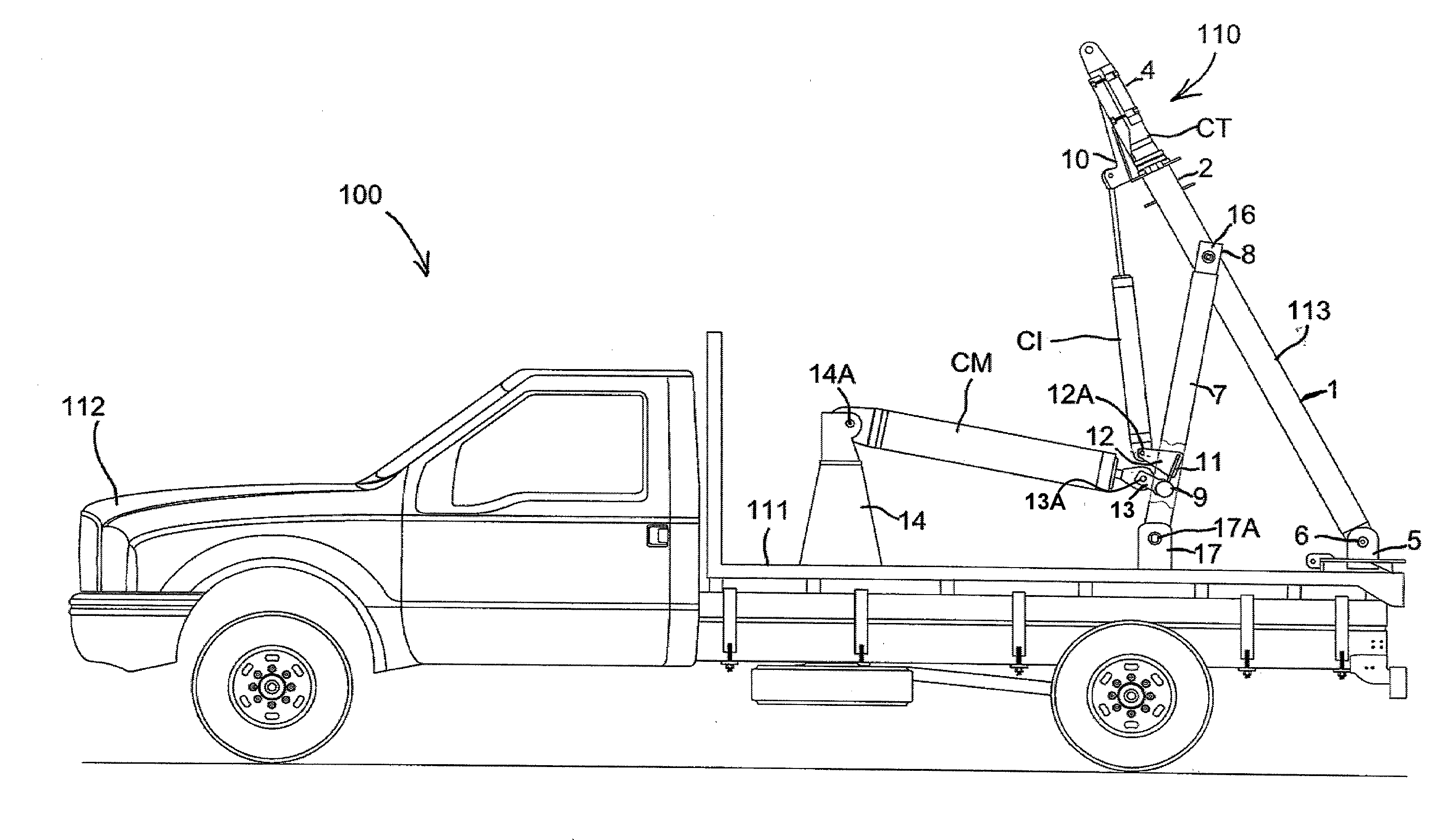
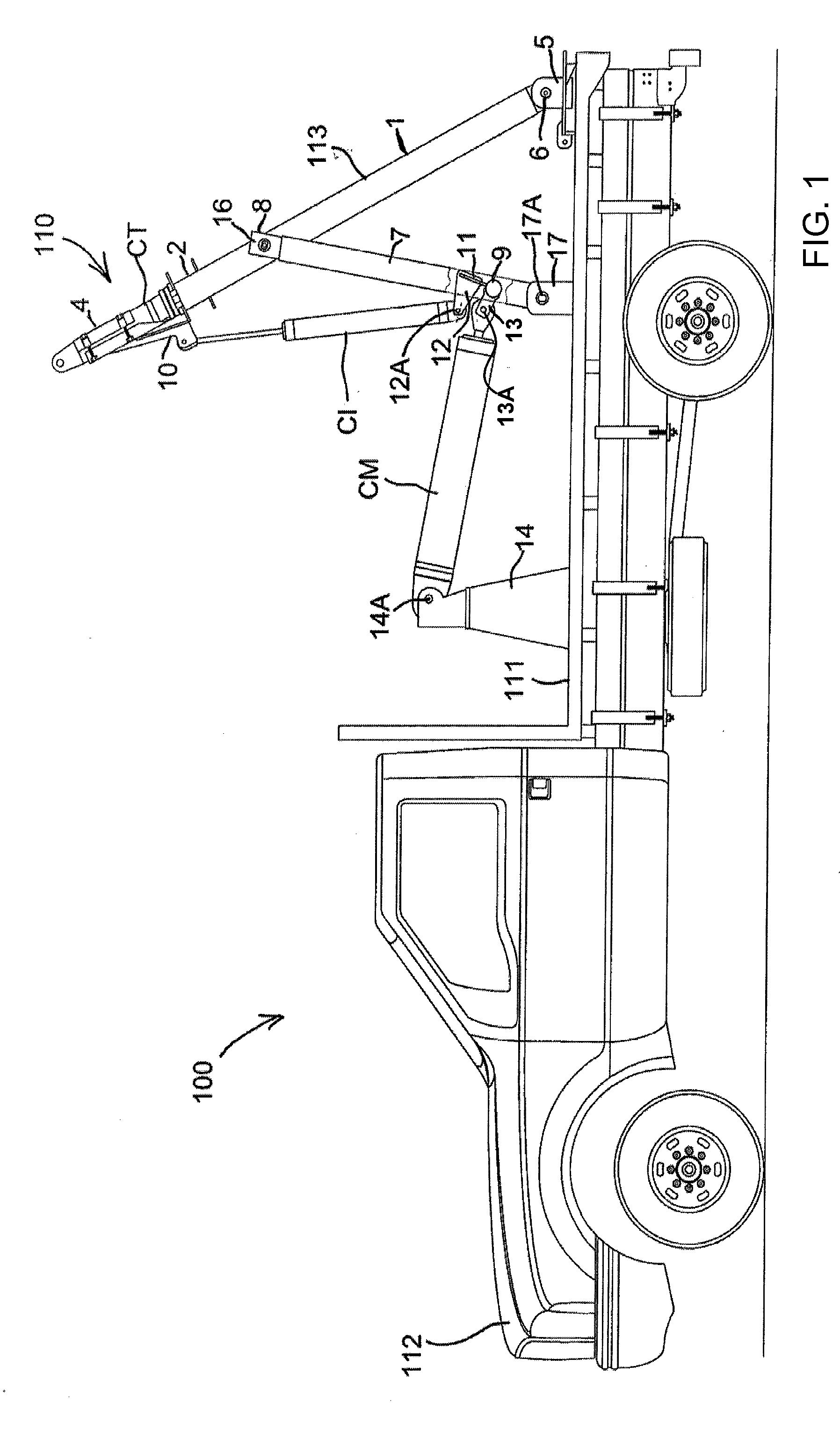
[0045]Referring now to the figures of the drawing in detail and first particularly to FIG. 1 thereof, there is shown a side view of a mobile testing device 100 in which the components thereof are set in a traveling position. The mobile testing device 100 includes a folding gantry 110 that is constructed on a moveable platform 111. The moveable platform 111 could be formed as part of a wheeled trailer or could be part of a motor vehicle. In the exemplary embodiment, the moveable platform 111 is shown as the rear bed of a suitably sized truck 112 that satisfies the required load capacity. The gantry 110 is formed from two spaced apart UPN type steel beams 1. Since FIG. 1 is a side view, only one of the beams 1 can be seen.

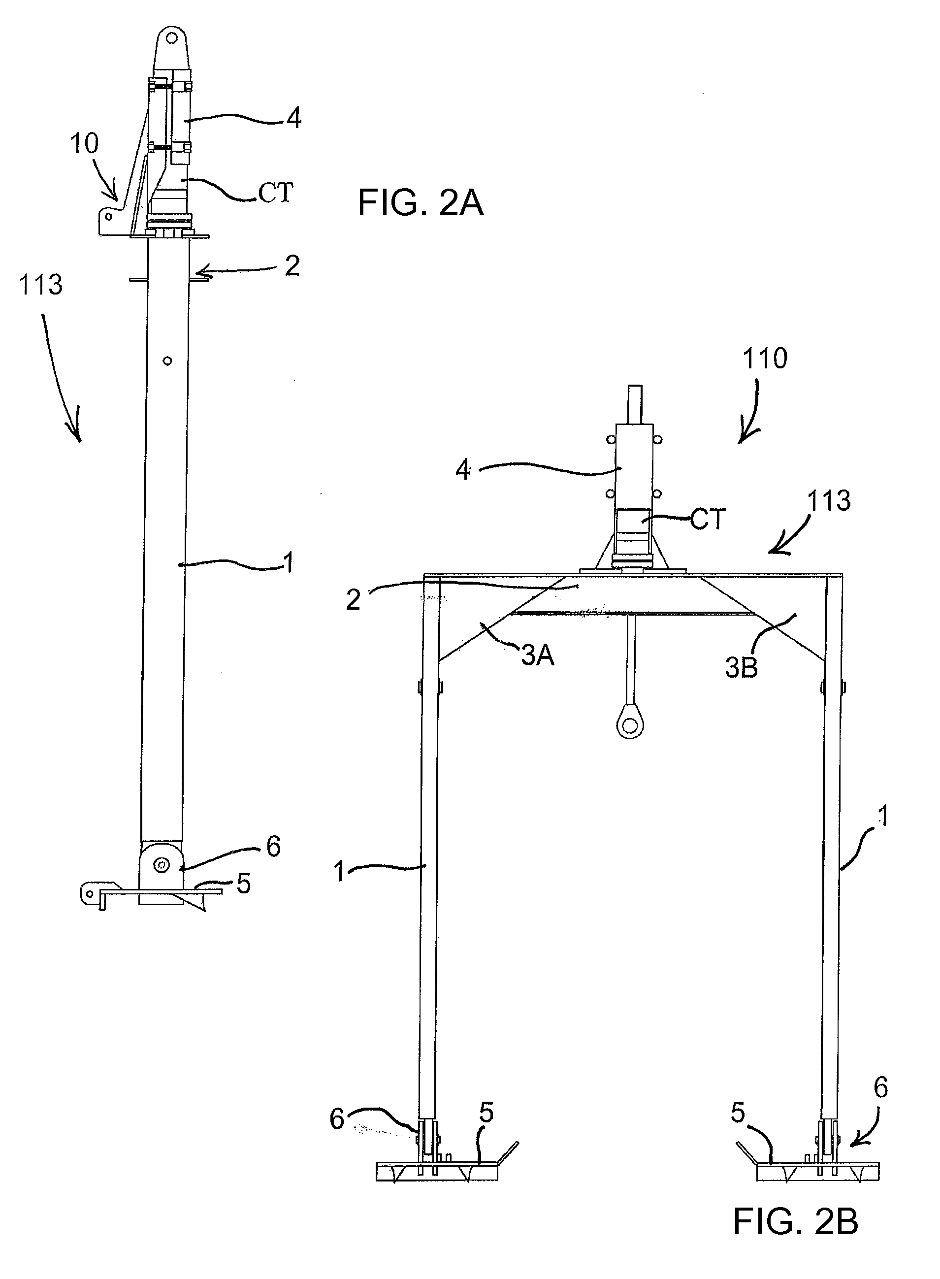
[0046]As can be seen in FIG. 2B, the gantry 110 includes a frame 113 and each of the beams 1 forms a column of the frame 113. FIG. 2A is a side view of the frame 113 and FIG. 2B is a rear view of the frame 113 (Note that components connecting the frame 113 to the pla...


PUM


Abstract

A mobile testing device is adjustable to perform different types of tension tests. The measuring device can conduct tests on components located on the ground or on elevated components. The measuring device can also carry out tensile strength tests on wire cables, slings, and other components. The measuring device can also be used to calibrate weight-indicating devices and instruments that indicate tensile strength. The positioning and movement of the gantry is achieved by using an assembly of hydraulic cylinders. Different working positions can thus be obtained and more than a trivial amount of physical effort is not required to operate the device.

Description

CROSS-REFERENCE TO RELATED APPLICATION[0001]This application claims the benefit under 35 U.S.C. § 119(a)-(d) of Application No. P-070100491 filed Feb. 6, 2007 in Argentina, and of Application No. 270422-07, filed Nov. 20, 2007 in Bolivia. As far as possible under the rules, the prior applications are herewith incorporated by reference in their entirety.BACKGROUND OF THE INVENTION[0002]1. Field of the Invention[0003]The invention generally relates to in-situ tensile testing of components that are subjected to tensile forces, wear, and deterioration, and the invention generally relates to calibrating weight-indicating instruments. More specifically, the invention relates to a mobile testing device and to a method of using the mobile testing device to perform in-situ tensile testing of such components and to calibrate such weight-indicating instruments.[0004]2. Description of the Related Art[0005]A number of different industrial areas use elements or components that are subjected to te...

Claims


Application Information

Patent Timeline
IPC IPC(8): G01N3/08
CPCG01N3/08G01N2203/028G01N2203/0244G01N2203/021
Inventor BERRA, VICTOR
Owner PETROIL
Why Eureka
Try Eureka