Multiple-ratio dual clutch vehicle transmission

a dual clutch, transmission technology, applied in fluid gearings, gearings, transportation and packaging, etc., can solve the problems of added weight, complexity, added cost to the powertrain, etc., and achieve the effect of low ratio and added overdrive ratio

Inactive Publication Date: 2008-08-07
EATON CUMMINS AUTOMATED TRANSMISSION TECH LLC
View PDF8 Cites 17 Cited by
  • Summary
  • Abstract
  • Description
  • Claims
  • Application Information

AI Technical Summary

Benefits of technology

The invention allows for two sets of ratio change clutches that work together with existing gear pairs to create a wider variety of ratios than what would normally be possible without extra equipment like range gearing or double headers. These clutches allow for smooth shifting between different levels of speed and power output, making it easier to drive the car and use its capabilities.

Problems solved by technology

This patent discusses different ways to improve power transmission in vehicles' engines. One way is through a variety of gear ratios in a single transmission system. Another method involves adding extra gearing called range gearing, which allows for more flexibility in meeting torque needs without requiring expensive and complex components like additional heads and clutches. Different techniques are described for controlling the engagement and disengagement of duel clutch discs in order to achieve smooth shifting between gears. Overall, the technical problem addressed in this patent is how to provide efficient and flexible power transmission systems for cars and trucks while minimizing costs and complexity.

Method used


Image

  • Multiple-ratio dual clutch vehicle transmission
  • Multiple-ratio dual clutch vehicle transmission

Examples


Embodiment Construction

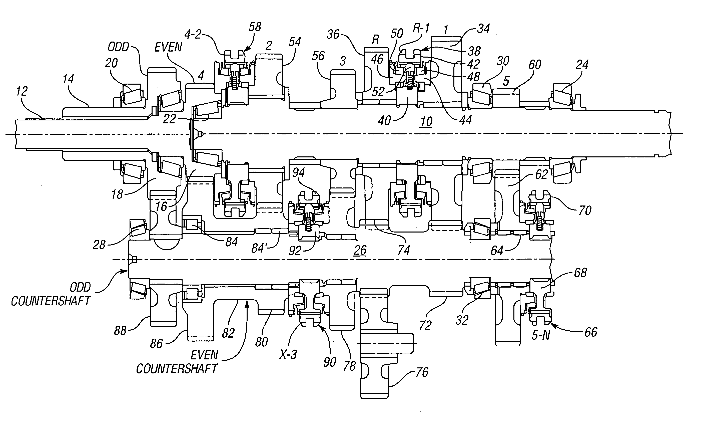
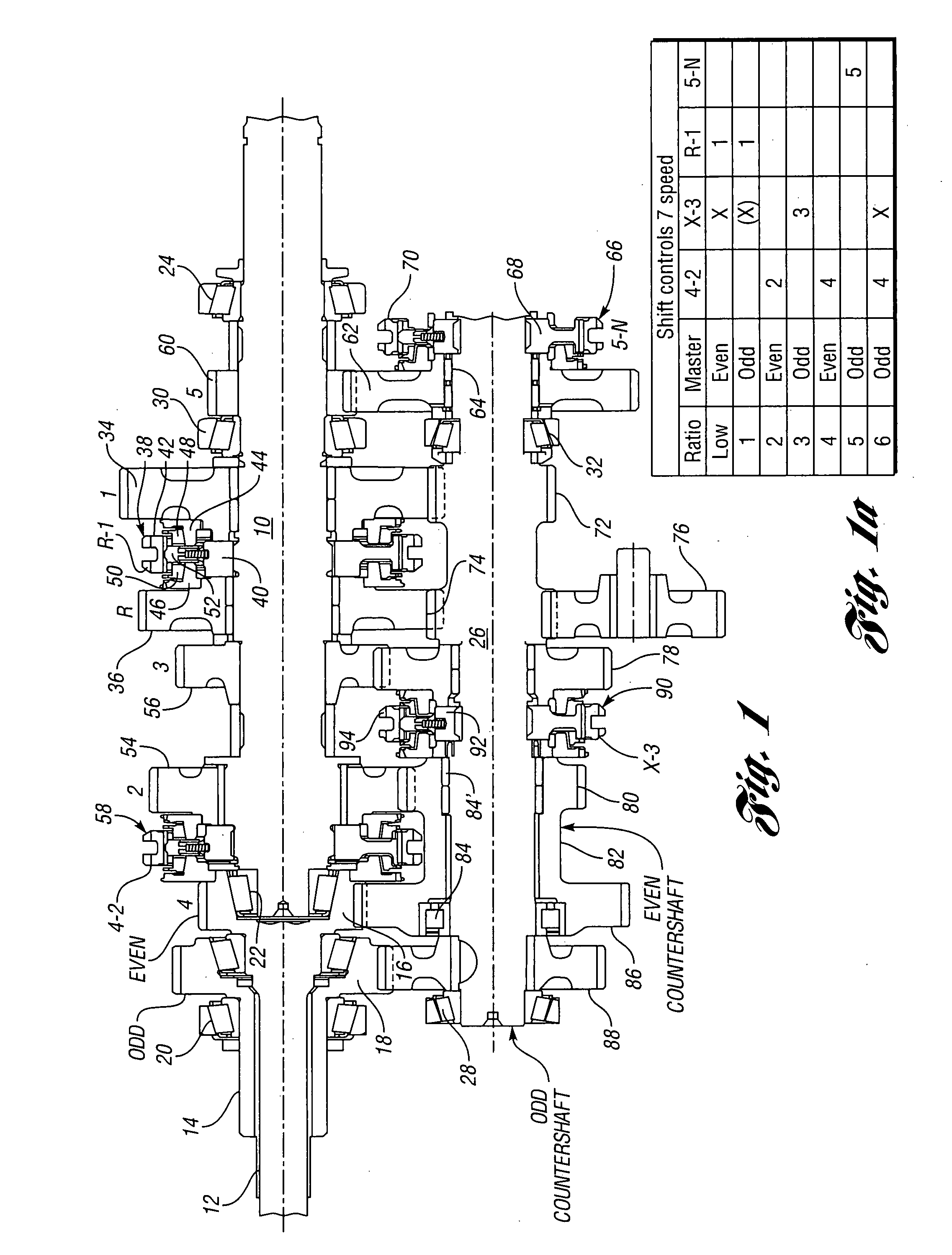
[0014]The transmission shown in FIG. 1 is a countershaft-type transmission having a mainshaft 10, which is integral with, or connected to, a power output shaft. A pair of power input shafts, as shown at 12 and 14, is drivably connected to an engine (not shown) through a master dual clutch assembly, as previously described. Power input shaft 14 is a sleeve shaft that surrounds power input shaft 12. Shafts 12 and 14 are connected drivably to a so-called “even” headset gear 16 and to a so-called “odd” headset gear 18. Gear 18 is journalled on a transmission housing (not shown) by a tapered roller bearing 20. Mainshaft 10 is journalled at its left end, as shown in FIG. 1, by tapered roller bearing 22 within a bearing cavity in even headset gear 16, as shown. The opposite end of mainshaft 10, which is the right end as illustrated in FIG. 1, is journalled in the transmission housing by bearing 24.

[0015]For convenience, the gears on the axis of mainshaft 10 involved during operation in rat...


PUM


Abstract

The disclosed multiple-ratio power transmission mechanism for a vehicle includes main transmission gearing and countershaft gearing that establish selectively plural power flow paths from an engine to vehicle traction wheels. Ratio change clutches are engageable selectively to establish power flow paths and pre-selected power flow during a ratio shift sequence throughout an extended overall ratio spread without a requirement for additional gearing.

Description


Claims


Application Information

Patent Timeline
Owner EATON CUMMINS AUTOMATED TRANSMISSION TECH LLC
Why Eureka
Try Eureka