Next generation hybrid III parallel/series hybrid system

a hybrid system and parallel/series technology, applied in the direction of electric propulsion mounting, jet propulsion mounting, transportation and packaging, etc., can solve the problem of very limited range, achieve the effect of increasing the fuel economy of heavy trucks, maximizing fuel economy, and reducing costs

a hybrid system and parallel/series technology, applied in the direction of electric propulsion mounting, jet propulsion mounting, transportation and packaging, etc., can solve the problem of very limited range, achieve the effect of increasing the fuel economy of heavy trucks, maximizing fuel economy, and reducing costs

US20080185198A1Inactive Publication Date: 2008-08-07JONES STEVEN MARK

Image

  • Next generation hybrid III parallel/series hybrid system
  • Next generation hybrid III parallel/series hybrid system
  • Next generation hybrid III parallel/series hybrid system

Examples


Embodiment Construction

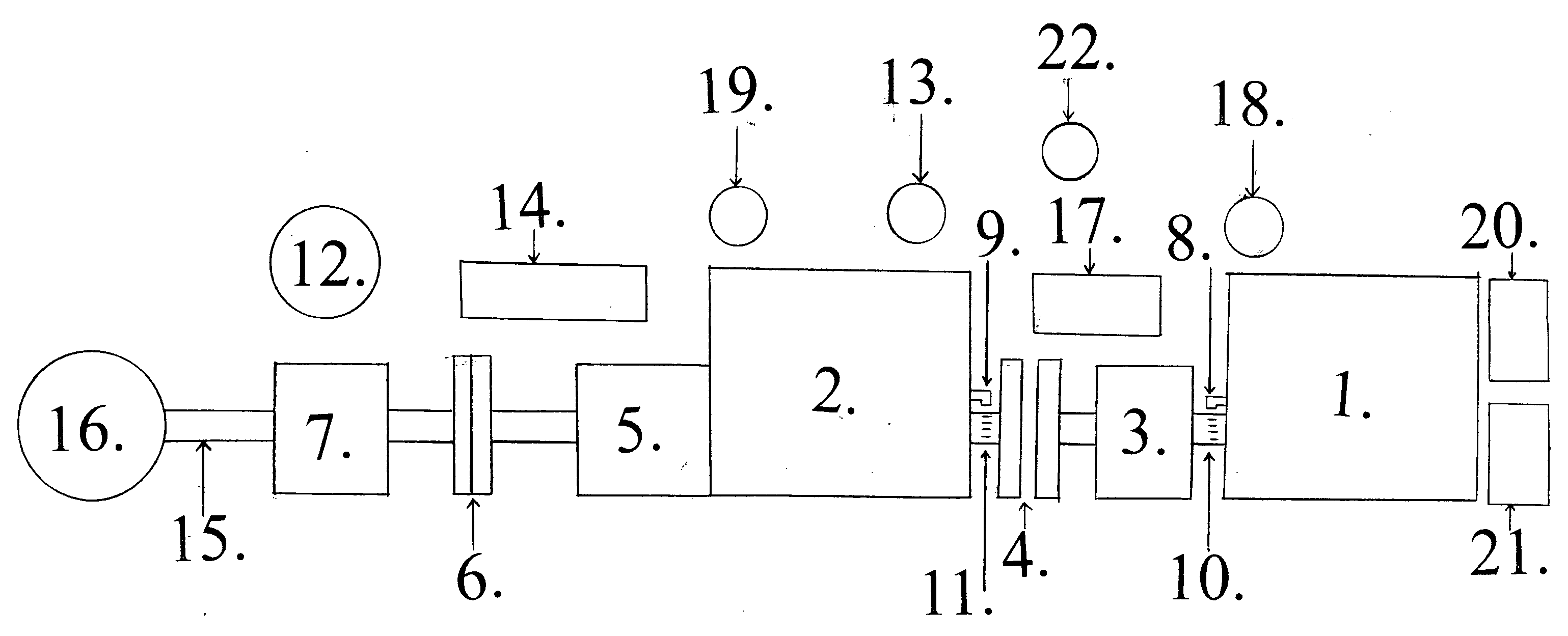
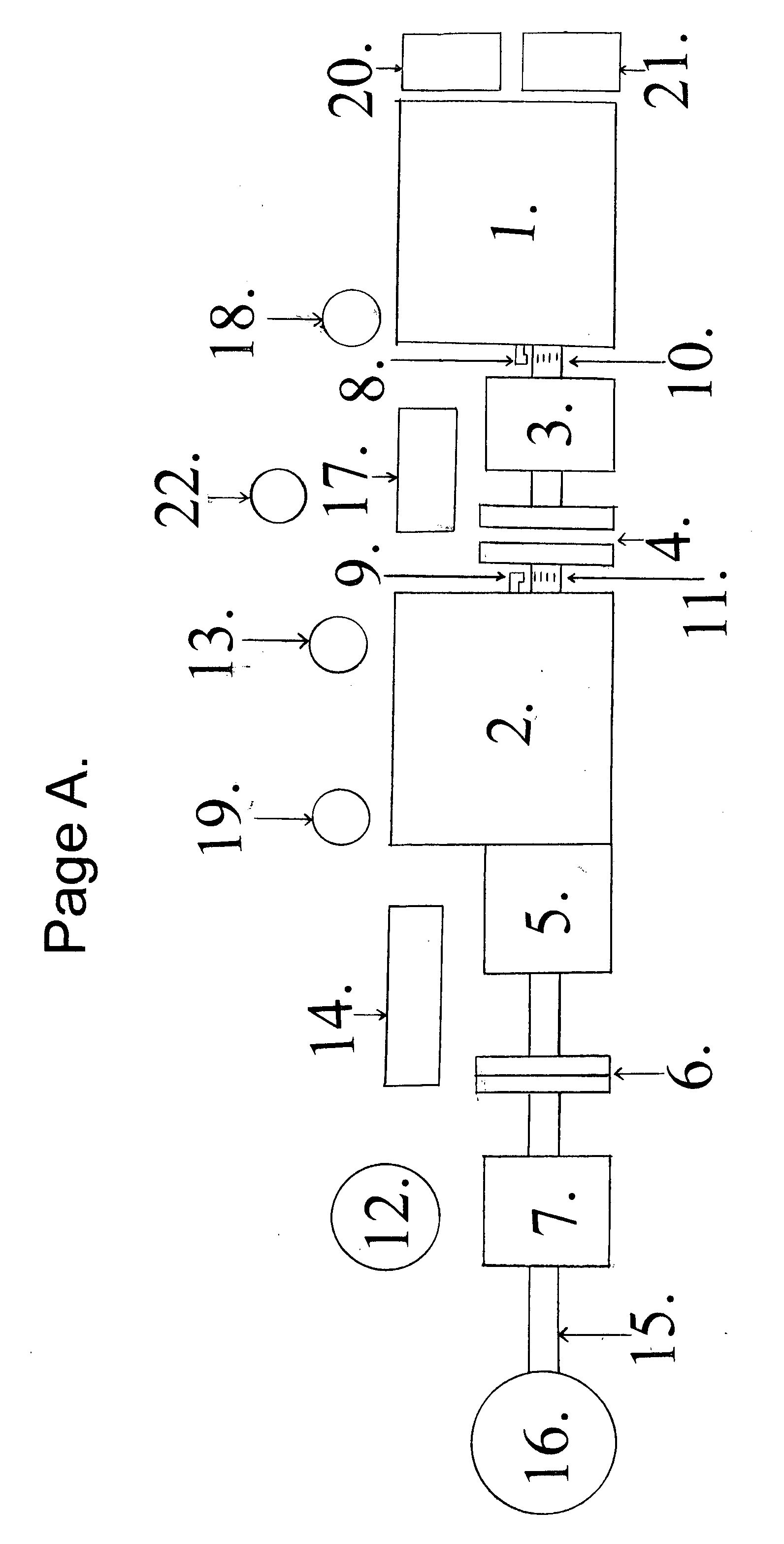
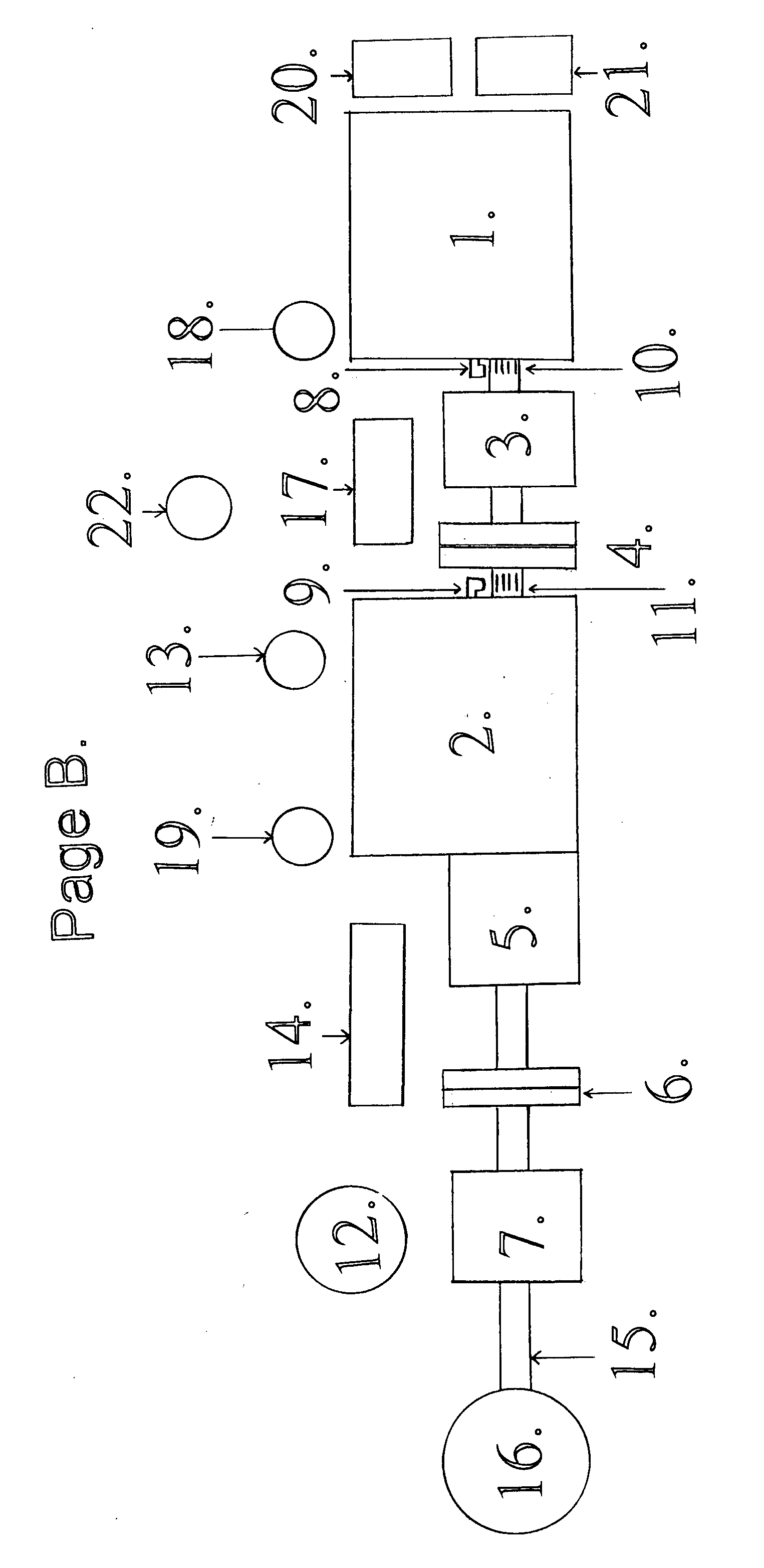
[0020]Components:[0021]1. Engine-A[0022]2. Engine-B[0023]3. Motor / generator connected to engine A.[0024]4. Automatic clutch between engine A and engine B.[0025]5. Transmission[0026]6. Automatic clutch between the transmission and the motor / generator connected to the driveshaft.[0027]7. Motor / generator connected to the driveshaft.[0028]8. Speed sensor on engine A.[0029]9. Speed sensor on engine B.[0030]10. Speed sensor strip on engine A.[0031]11. Speed sensor strip on engine B.[0032]12. Main control box.[0033]13. Throttle position sensor.[0034]14. Electrical storage unit.[0035]15. Driveshaft[0036]16. Differential.[0037]17. Heat exchanger[0038]18. Electric oil pump A.[0039]19. Electric oil pump B.[0040]20. Radiator on engine A[0041]21. Radiator on engine B[0042]22. Manual control hybrid selector

SUMMARY OF THE INVENTION

[0043]This invention relates to electric hybrid vehicles. There are basically three types of electric propulsion systems known for vehicles.

[0044]First, there is a pure ...


PUM


Abstract

This Next Generation Heavy Hybrid Propulsion System III was specifically designed to use mainly all off the components. This facilitates in the rapid deployment to market with minimum increased purchasing price to the truck over conventional propulsion systems.By designing a cost effective no frills hybrid system, allows more trucks to be equipped with this technology and reap the rewards of higher fuel economy. There is minimum research and development funds needed to place this technology on line. This technology can be used in small cars to large vehicles with similar results, increased fuel economy.

Description

CROSS-REFERENCE TO RELATED APPLICATIONS[0001]This application is related to and claims priory from Provisional Patent Application Ser. No. 60 / 899,190 Feb. 2, 2007.STATEMENT REGARDING FEDERALLY SPONSORED RESEARCH OR DEVELOPMENT[0002]“Not Applicable”REFERENCE TO A SEQUENCE LISTING, A TABLE, OR A COMPUTER PROGRAM LISTING[0003]“Not Applicable”BACKGROUND OF THE INVENTIONField of the Invention[0004]This invention was first conceived to help the heavy hybrid technology reach its fullest potential in fuel economy, at an economical approach. To achieve this goal, I designed an innovating engine and motor / generator layout for maximum power and fuel economy.[0005]The Next Generation Heavy Hybrid Propulsion System III technology is a spin off of my Dual Hybrid Propulsion System and Next Generation Heavy Hybrid Propulsion System II.[0006]This technology uses a novel approach to maximize fuel economy by using two independently operated engines and motor / generators to maximize fuel efficiency with...

Claims


Application Information

Patent Timeline
07 Aug 2008
Publication
US20080185198A1
IPC
B60K6/00
CPC
B60K5/08; Y02T10/6234; B60Y2200/14; B60K6/442; Y02T10/62
Inventors
JONES, STEVEN MARK