Electric parking brake control apparatus, electric parking brake system, and method for controlling electric parking brake system

a technology of electric brakes and control apparatuses, which is applied in the direction of braking systems, braking components, transportation and packaging, etc., can solve the problems of increasing the cost and size of actuators, the decrease of hydraulic pressure, and the vehicle starting to move, so as to reduce the size of the actuator, and reduce the effect of a target tension

Active Publication Date: 2008-08-07
TOYOTA JIDOSHA KK
View PDF7 Cites 34 Cited by
  • Summary
  • Abstract
  • Description
  • Claims
  • Application Information

AI Technical Summary

Benefits of technology

[0009]The invention provides an electric parking brake control apparatus, an electric parking brake system, and a method for controlling an electric parking bra

Problems solved by technology

However, if the hydraulic brake is released, there is a possibility that the vehicle will start moving due to the lack of tension caused by the loss of tension.
On the other hand, if the hydraulic brake is

Method used


Image

  • Electric parking brake control apparatus, electric parking brake system, and method for controlling electric parking brake system
  • Electric parking brake control apparatus, electric parking brake system, and method for controlling electric parking brake system
  • Electric parking brake control apparatus, electric parking brake system, and method for controlling electric parking brake system

Examples


first embodiment

of the Invention

[0056]FIG. 4A is a timing chart showing time-changes in an ON signal from the switch 8, an ON-signal from the electric motor 31, the wheel cylinder pressure, and the value detected by the tension sensor. FIG. 4B is a flowchart showing the routine according to which the brake ECU 9 controls the wheel cylinder pressure and the tension.

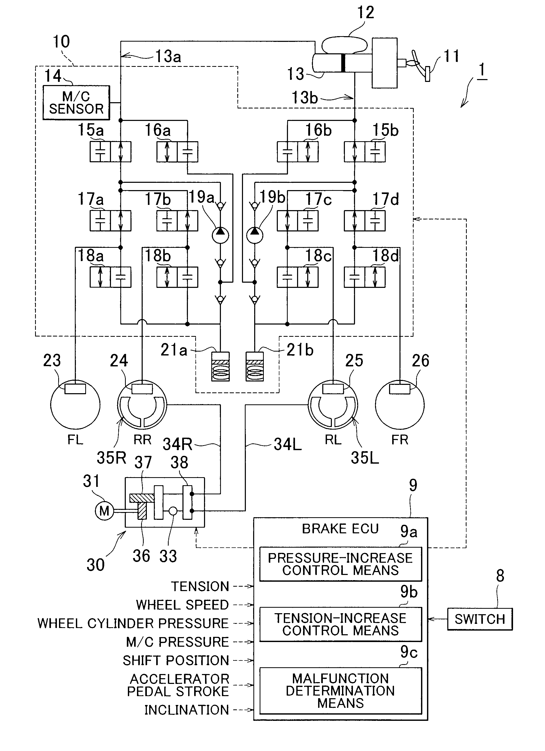
[0057]The brake ECU 9 determines whether the switch 8 is on. When the switch 8 is on, the brake ECU 9 detects an ON signal (S 1).

[0058]When it is determined that the switch 8 is on, the pressure-increase control means 9a controls the brake actuator 10 to increase the wheel cylinder pressures at the rear wheels RR and RL to the target value (S2).

[0059]When the wheel cylinder pressures reach the target value, the tension-increase control means 9b drives the electric motor 31 to pull the cables 34R and 34L until the target tension is achieved (S3).

[0060]When the target tension is achieved, the tension-increase control means 9b stops the elec...

second embodiment

of the Invention

[0063]In the electric parking brake system 1 according to a second embodiment of the invention, the target value of the wheel cylinder pressure is set to the wheel cylinder pressure actually selected by the driver, whereby the load on the electric motor 31 is further reduced.

[0064]FIG. 5A is a timing chart showing time-changes in an ON signal from the switch 8, an ON-signal from the electric motor 31, the wheel cylinder pressure, and the value detected by the tension sensor. FIG. 5B is a flowchart showing the routine according to which the brake ECU 9 controls the wheel cylinder pressure and the tension. In FIG. 5B, the same step numbers are assigned to the steps that are the same as those in FIG. 4B. Because the routine in FIG. 5B differs from the routine in FIG. 4B only in step S12, step S12 will be described in detail below.

[0065]When it is determined that the switch 8 is on, the pressure-increase control means 9a controls the brake actuator 10 to increase the whe...

third embodiment

of the Invention

[0067]In the electric parking brake system 1 according to a third embodiment of the invention, if the hydraulic brake has already been applied when the switch 8 is turned on, the parking brake units 35R and 35L are brought into the braking state using the wheel cylinder pressure as the target value.

[0068]FIG. 6A is a timing chart showing time-changes in an ON signal from the switch 8, an ON-signal from the electric motor 31, the wheel cylinder pressure, and the value detected by the tension sensor. FIG. 6B is a flowchart showing the routine according to which the brake ECU 9 controls the wheel cylinder pressure and the tension.

[0069]The brake ECU 9 determines whether the switch 8 is on. When the switch 8 is on, the brake ECU 9 detects an ON-signal (S21).

[0070]When an ON-signal is detected, the brake ECU 9 determines whether the hydraulic brake has been applied (S22). Whether the hydraulic brake has been applied is determined based on, for example, whether the wheel c...


PUM


Abstract

An electric parking brake control apparatus includes: an electric parking brake actuator that pulls cables connected to respective parking brake units of wheels; a brake actuator that controls braking pressures applied to the wheels by service brakes; a pressure-increase control unit that controls the brake actuator to increase the braking pressures to a predetermined value, when a tension of the cables falls below a predetermined target tension after the cables are pulled until the target tension is achieved; and a tension-increase control unit that controls the electric parking brake actuator to pull the cables until the tension of the cables exceeds the target tension, after the brake pressures are increased by the pressure-increase control unit.

Description

INCORPORATION BY REFERENCE[0001]The disclosure of Japanese Patent Application No. 2007-23379 filed on Feb. 1, 2007 including the specification, drawings and abstract is incorporated herein by reference in its entirety.BACKGROUND OF THE INVENTION[0002]1. Field of the Invention[0003]The invention relates to an electric parking brake control apparatus that controls an electric parking brake system of a vehicle, an electric parking brake system, and a method for controlling an electric parking brake system.[0004]2. Description of the Related Art[0005]A vehicle brake system is required to serve two functions, that is, a function as a service brake (hereinafter, referred to as “hydraulic brake”) that decelerates or stops a vehicle in motion, and a function as a parking brake that maintains the vehicle at standstill. A brake system that performs two functions using a shared structure has been suggested in order to suppress increases in the number of components and cost. A technology in whi...

Claims


Application Information

Patent Timeline
IPC IPC(8): B60T13/74F16D65/14F16D66/00
CPCB60T7/042B60T13/686B60T8/32
Inventor SUZUKI, MASAKUNI
Owner TOYOTA JIDOSHA KK
Why Eureka
Try Eureka