Non-invasive method to identify hidden foreign objects near a human subject

a technology of hidden foreign objects and detection methods, applied in the direction of detection/prospecting using thermal methods, material testing goods, instruments, etc., can solve the problems of x-ray and microwave radiation is dangerous to people, and cannot be used to scan objects on or near living humans

Active Publication Date: 2008-08-07
SMOLIAK YAFIM +1
View PDF3 Cites 23 Cited by
  • Summary
  • Abstract
  • Description
  • Claims
  • Application Information

AI Technical Summary

Benefits of technology

[0024]According to still further features in the described preferred embodiments, the first frequency band of the radiation includes a wide range of wavelengths spanning from a minimum wavelength of less than 5 μm till a maximum wavelength of greater than 12 μm.
[0025]According to still further features in the desc

Problems solved by technology

Unfortunately, x-rays and microwave radiation have the drawback that they are active methodologies requiring exposing objects to high-energy beams of x-ray or microwave radiation.
These x-ray and microwave beams are dangerous to people and cannot be used for scanning objects on or near living humans.
Metal detectors are safe for use in the vicinity of humans but suffer from two drawbacks.
First metal detectors only identify one particular class of dangerous object (those made of metal) but cannot identify other dangerous objects (such as organic explosives, plastic or ceramic weapons, various toxic substances or biological agents).
Furthermore, metal detectors are non-specific and cannot differentiate between weapons and benign metal objects of common occurrence (e.g. coins, surgical implants, keys, electronic devices, buttons, zippers) Therefore, where metal detectors are used, a (sometimes lengthy) secondary screening is necessary to preclude non-metallic threats and to determine the nature of detected metal objects.
Such intrusive methods are time consuming, inconvenient, may lead to conflict between security personnel and the public.
Reliable routine security systems based on such methodologies are extremely expensive and prob

Method used


Image

  • Non-invasive method to identify hidden foreign objects near a human subject
  • Non-invasive method to identify hidden foreign objects near a human subject
  • Non-invasive method to identify hidden foreign objects near a human subject

Examples


first embodiment

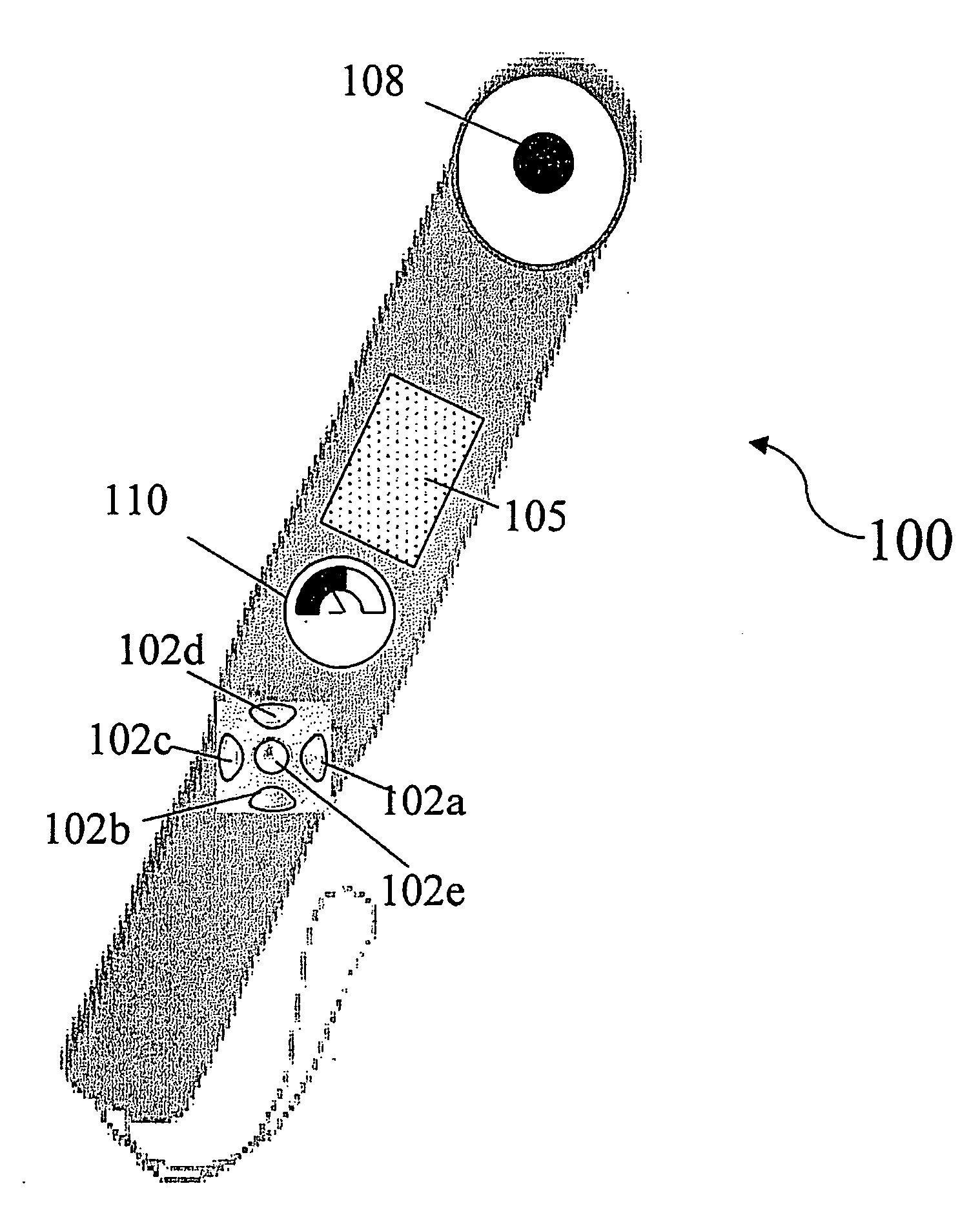
[0079]We refer now to FIG. 13, a flow chart of the present invention. In FIG. 13 a security guard is using the scanning device of FIG. 14 to test for a foreign objects. First the guard measures 13 the integral background radiation level (unmodified by the presence of foreign object 8).

[0080]In the embodiment of FIG. 13, a human operator using a hand held instrument 100 (see FIG. 14) measures 13 an integral background radiation level and calibrates for an integral scan 12 by holding the sensor 108 over a part of subject 1, where there is no hidden object and where the radiation emitted by subject 1 is substantially unmodified by foreign object 8. Sensor 108 is a pyroelectric detector. The pyroelectric detector is sensitive to IR radiation in the bandwidth from 5 μm -20 μm. Thus, integral scan 12 measures the average radiation intensity in this wide bandwidth. To measure 13 the background radiation level and calibrate the instrument, the operator first puts instrument 100 into a integ...

second embodiment

[0094]We now refer to FIG. 15, the current invention. The embodiment of FIG. 15 includes multiple sensors assemblies 208a, 208b, 208c, and 208d. Each sensor assembly 208a-208d, is configured to perceive radiation in a different bandwidth. Particularly, sensor assembly 208a is configured to be sensitive to radiation in a wide spectrum from 5 μm-20 μm; sensor assembly 208b is configured to be sensitive to radiation from 4.5 μm-5.5 μm; sensor assembly 208c is configured to be sensitive to radiation from 13.5 μm-14.5 μm; and sensor assembly 208d is configured to be sensitive to radiation from 9.5 μm-10.5 μm.

[0095]The embodiment of FIG. 15 of an instrument 200 is supplied with two buttons, and on-button 202a and a background-calibration-button 202b. When on-button 202a and background-calibration-button 202b are depressed simultaneously, instrument 200 measures and detects a background radiation level simultaneously with all four sensor assemblies 208a-208d and stores a background level f...

third embodiment

[0098]FIG. 16 illustrates an instrument 300 to detect and identify foreign object 8 according to the present invention. A fill body scanner 302 contains sensors configured to scan across a subject 1. Full body scanner 302 may be a simple metal detector, or it may include more sophisticated sensors. If fast conclusive results are important and money is not an object, full body scanner may contain multiple IR sensor assemblies. Full body scan results are sent to a desktop computer 306. Desktop computer 306 conveys an image 308 of subject 1 to a display device 310 (a computer monitor). Also output to the display device 310 is a label 312, showing the state of identification of foreign objects in the vicinity of subject 304. For objects that are not yet fully identified, the operator has a hand scanner instrument 200, which is also integrated to desktop computer 306. Thus, when the operator scans an unidentified object with instrument 200, the output of instrument 200 is registered by d...


PUM


Abstract

A method and device are revealed to non-invasively identify hidden foreign objects in proximity of living tissue. More specifically to a method and device find a foreign object hidden under the clothes of a person by measuring an anomaly in an infrared radiation signal emitted by the human subject; the anomaly caused by the presence of the foreign object. A spectral scan at the identified location is used to identify the object. Even when the object is hidden behind clothes, the object is positively identified based on the interaction of optical radiation naturally emitted by the human body in the infrared frequency spectrum with every component of the examined object.

Description

[0001]This is a continuation-in-part of U.S. Provisional Patent Application No. 60\694238, filed Jun. 28, 2005 AND 60\708389 filed Aug. 16, 2005.FIELD AND BACKGROUND OF THE INVENTION[0002]The present invention relates to a method and device to non-invasively identify hidden foreign objects in proximity of living tissue and more specifically to a method and device that to detect and identify foreign objects hidden under the clothes of a person by measuring an infrared radiation signal emitted by the human subject and by measuring a change in the radiation signal caused by the presence of the foreign object.[0003]The present invention is in the class of methods for structural analysis of multi-component materials. The particular multi-component structures / materials of interest include the following components: a human body (living tissue), clothes, and a foreign object that is composed one or more materials and may include metal, magnetic materials, conductive materials or dielectric ...

Claims


Application Information

Patent Timeline
IPC IPC(8): G01J5/02
CPCG01J5/0022G01J5/0025G01V9/005G01N33/22G01N21/3581
Inventor LYUBCHIK, YAKOVSMOLYAK, YAFIMBLAUNSHTEIN, NATHAN
Owner SMOLIAK YAFIM
Why Eureka
Try Eureka