Transponder systems and methods for radio-over-fiber (ROF) wireless picocellular systems

a wireless picocellular and transponder technology, applied in the field of wireless communication systems, can solve the problems of difficult scaling, difficult distribution and use, and limited radiation pattern of transponder antennas, and achieve the effect of enhancing antenna directivity and enhancing antenna directivity

Active Publication Date: 2008-08-07
CORNING OPTICAL COMM LLC
View PDF99 Cites 64 Cited by
  • Summary
  • Abstract
  • Description
  • Claims
  • Application Information

AI Technical Summary

Benefits of technology

[0012]One aspect of the invention is a transponder system with enhanced antenna directivity, for use in a RoF wireless picocellular system. The system includes a transponder having a converter pair unit adapted to convert radio-frequency (RF) electrical signals into optical signals and vice versa, and an antenna syste

Problems solved by technology

This makes the wireless system/network relatively complex and difficult to scale, particularly when many picocells need to cover a large region.
Further, the digital information processing performed at the access point devices requires that these devices be activated and controlled by the head-end controller, which further complicates the distribution and use of numerous access point devices to produce a large picocellular coverage area.
While RoF wireless picocellular systems are generally robust, there are some limitations.
One limitation relates to the radiation pattern from the transponder antenna.
Though microstrip antenna

Method used


Image

  • Transponder systems and methods for radio-over-fiber (ROF) wireless picocellular systems
  • Transponder systems and methods for radio-over-fiber (ROF) wireless picocellular systems
  • Transponder systems and methods for radio-over-fiber (ROF) wireless picocellular systems

Examples


Embodiment Construction

[0056]Reference is now made in detail to the present preferred embodiments of the invention, examples of which are illustrated in the accompanying drawings. Whenever possible, the same or analogous reference numbers are used throughout the drawings to refer to the same or like parts.

Generalized Optical-Fiber-Based RoF Wireless Picocellular System

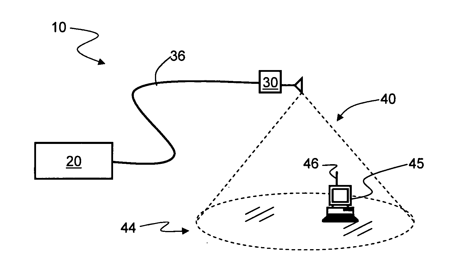
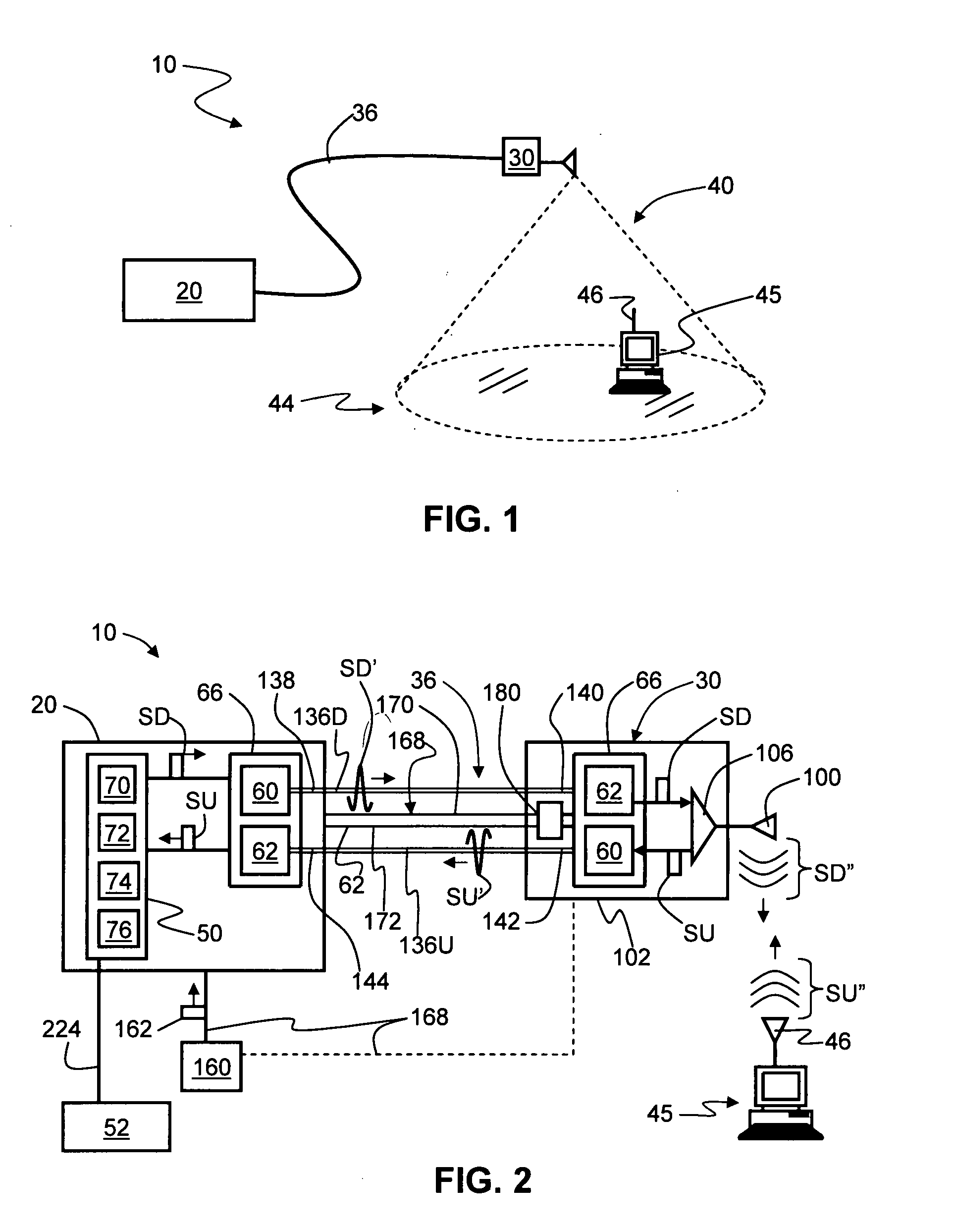
[0057]FIG. 1 is a schematic diagram of a generalized embodiment of an optical-fiber-based RoF wireless picocellular system 10 according to the present invention. System 10 includes a head-end unit 20, one or more transponder units (“transponder”) 30 and an optical fiber RF communication link 36 that optically couples the head-end unit to the transponder. In an example embodiment, optical fiber RF communication link 36 includes at least one optical fiber, and preferably two optical fibers (e.g., uplink and downlink optical fibers, as discussed below). As discussed in detail below, system 10 is adapted to form a picocell 40 substantially cente...


PUM


Abstract

Transponder systems and methods for radio-over-fiber (RoF) wireless picocellular system are disclosed. One type of transponder system includes a RoF transponder used in combination with at least one radiation-reflector assembly to provide for enhanced antenna directivity of the transponder. Another type of transponder system is a transponder node assembly, wherein two or more transponders are integrated into a single assembly, thereby reducing cost while facilitating RoF wireless picocellular system deployment. Another type of transponder system provides one or more transponders in a RoF wireless picocellular system with radio-frequency identification (RFID) tags, and uses an RFID tag reader to locate and read information from the transponders, as well as to perform transponder mode selection. Another type of transponder system is directed to a tether cable assembly that includes a dispensible/retractable coiled tether cable housed in a protective housing for connecting the tether cable to a transponder.

Description

BACKGROUND OF THE INVENTION[0001]1. Field of the Invention[0002]The present invention relates generally to wireless communication systems, and in particular relates to transponders and transponder systems and methods used in optical-fiber-based wireless picocellular systems for radio-over-fiber (RoF) communication.[0003]2. Technical Background[0004]Wireless communication is rapidly growing, with ever-increasing demands for high-speed mobile data communication. As an example, so-called “wireless fidelity” or “WiFi” systems and wireless local area networks (WLANs) are being deployed in many different types of areas (coffee shops, airports, libraries, etc.). Wireless communication systems communicate with wireless devices called “clients,” which must reside within the wireless range or “cell coverage area” in order to communicate with the access point device.[0005]One approach to deploying a wireless communication system involves the use of “picocells,” which are radio-frequency (RF) c...

Claims


Application Information

Patent Timeline
IPC IPC(8): H04Q9/00
CPCG06K7/10178H04W88/085H04B10/25756G06K19/0723
Inventor GEORGE, JACOBKOBYAKOV, ANDREYSAUER, MICHAELHURLEY, WILLIAM CARL
Owner CORNING OPTICAL COMM LLC
Why Eureka
Try Eureka