Hologram optical element, method of fabrication thereof, and image display apparatus

a technology of optical elements and holograms, applied in the field of hologram optical elements, method of fabrication thereof, and image display apparatus, can solve the problems of difficult stably producing holograph combiners, difficult to accurately adjust the positions of eccentric lenses in the exposure optical system designed for different wavelengths, and inability to satisfy the simultaneous correction of type-1 and type-2 aberrations, etc., to achieve satisfactory simultaneous correction, stable acquisition, and simple optical construction

Inactive Publication Date: 2008-08-07
KONICA MINOLTA INC
View PDF5 Cites 28 Cited by
  • Summary
  • Abstract
  • Description
  • Claims
  • Application Information

AI Technical Summary

Benefits of technology

[0017]According to the invention, it is possible to stably obtain a hologram optical element that has a simple optical construction suitable for mass fabrication, that allows satisfactory simultaneous correction for two kinds of chromatic aberration, and that offers satisfactory optical performance.

Problems solved by technology

Inconveniently, however, according to JP-A-2004-219497, it is difficult to accurately adjust the positions of the eccentric lenses in the exposure optical systems designed for different wavelengths and to accurately arrange at the exposure positions for the different wavelengths the substrate having the hologram photosensitive material bonded thereto.
Thus, it is difficult to stably produce a holograph combiner.
On the other hand, JP-A-2004-325542 is originally intended to correct for type-1 aberration, and attempting to correct for type-2 aberration by the same method causes the following new inconveniences, making satisfactory simultaneous correction for type-1 and type-2 aberrations impossible.
Moreover, if there are large differences in angle of incidence among the reference beams of different wavelengths at the time of exposure, notable color shifting may occur as the viewer moves his eyes up and down, leading to poor image quality.
Thus, even when the glass material for the prism is optimized, it is difficult to satisfactorily correct for type-2 aberration ascribable to those deviations.

Method used


Image

  • Hologram optical element, method of fabrication thereof, and image display apparatus
  • Hologram optical element, method of fabrication thereof, and image display apparatus
  • Hologram optical element, method of fabrication thereof, and image display apparatus

Examples


first embodiment

[0037]An embodiment of the invention will be described below with reference to the relevant drawings.

1. Construction of an HMD

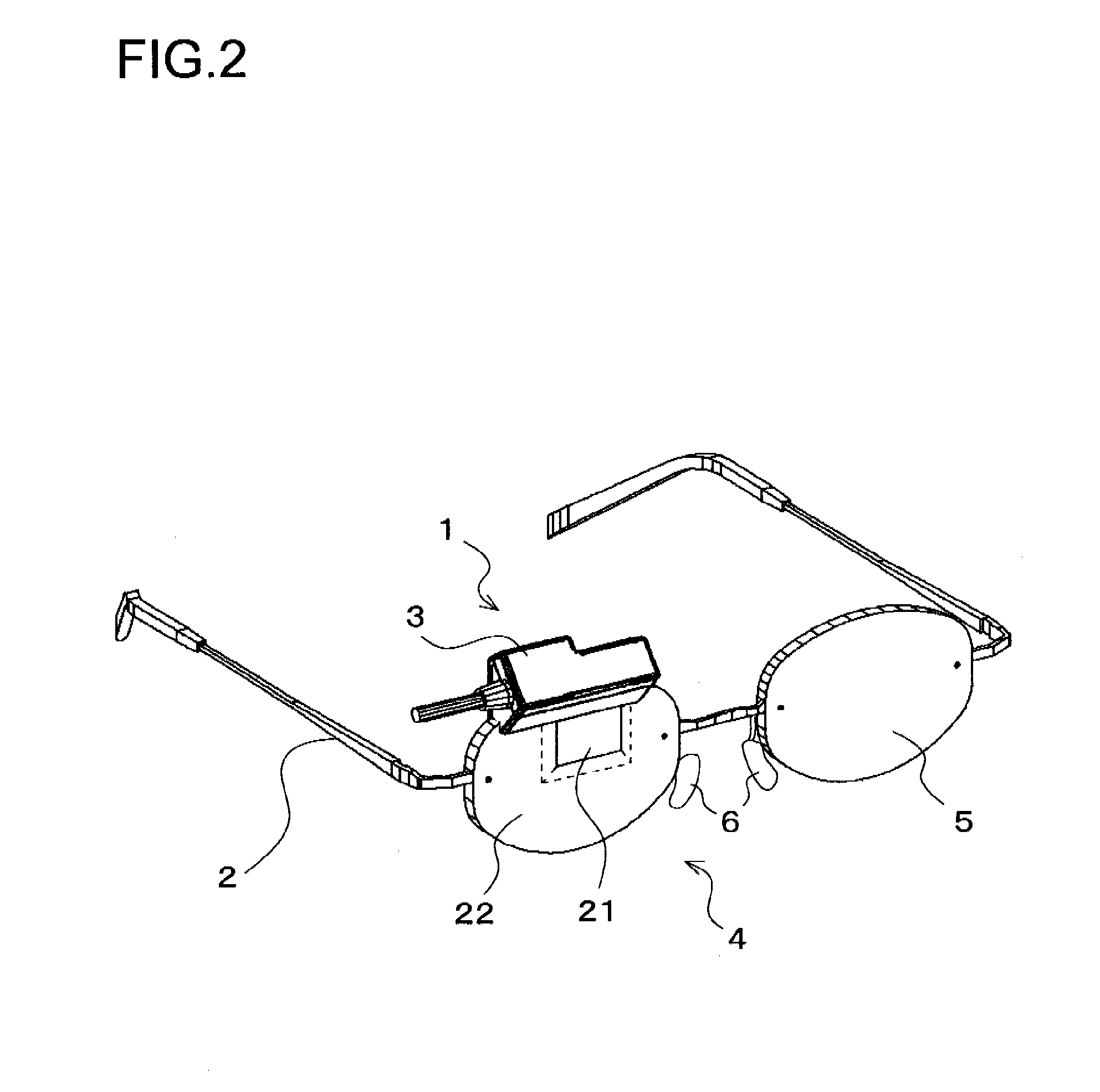
[0038]FIG. 2 is a perspective view showing an outline of the construction of an HMD according to the first embodiment. The HMD is composed of an image display apparatus 1 and a supporting member 2.

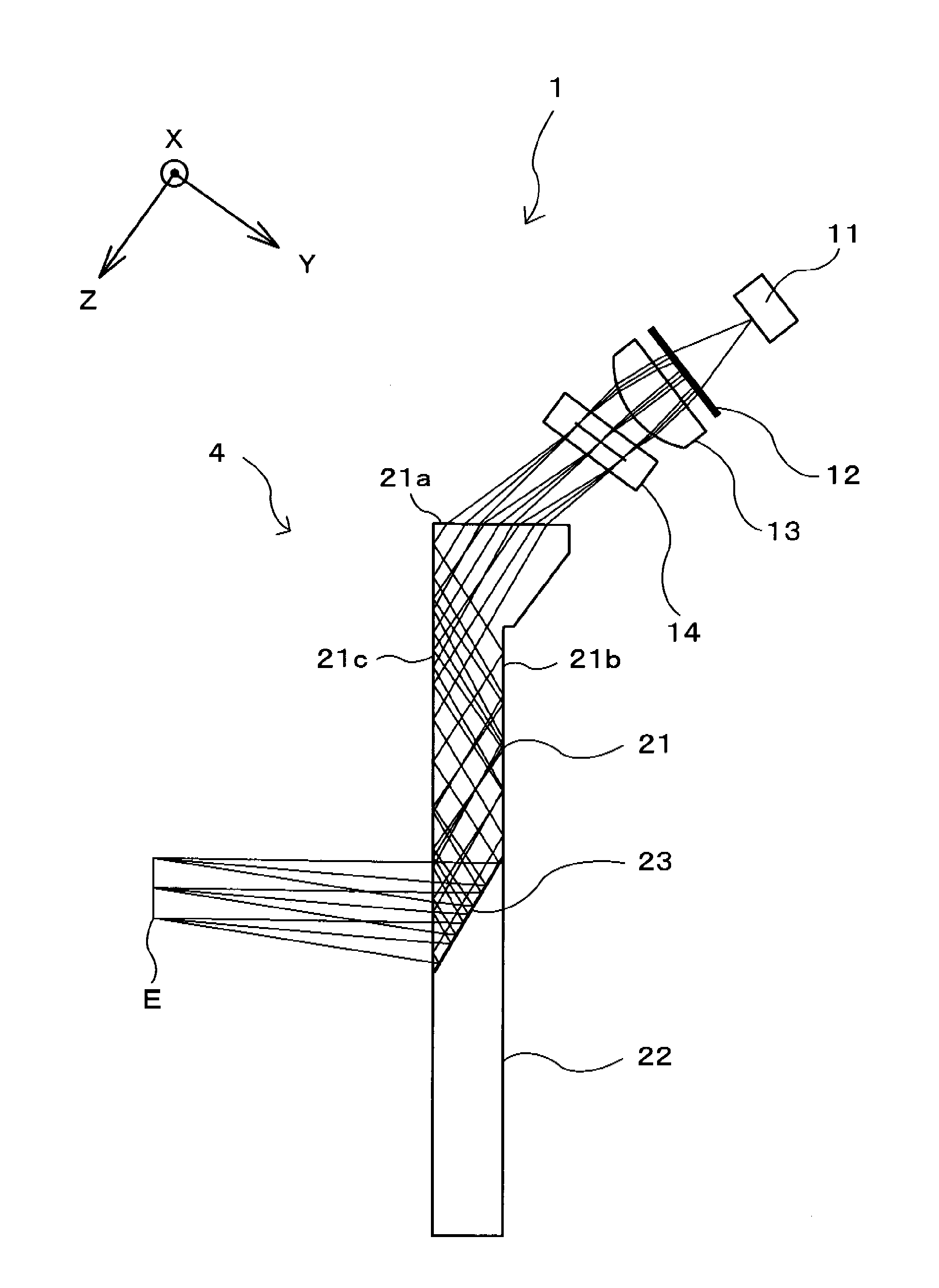
[0039]The image display apparatus 1 has a casing 3, which houses at least a light source 11 and a display element 14 (for both, see FIG. 3). The casing 3 holds part of an eyepiece optical system 4. The eyepiece optical system 4 is composed of an eyepiece prism 21 and a deflecting prism 22 bonded together, of which both will be described later, and is as a whole shaped like one lens (in FIG. 2, the one for the right eye) of eyeglasses. The image display apparatus 1 also includes a circuit board (unillustrated) for feeding the light source 11 and the display element 14 with at least drive electric power and an image signal via a cable (unillustrated) through the casin...

second embodiment

[0109]Another embodiment of the invention will be described below with reference to the relevant drawings. In the following description, for the sake of convenience of explanation, such members as find their counterparts in the first embodiment are identified by common reference signs and no overlapping description will be repeated.

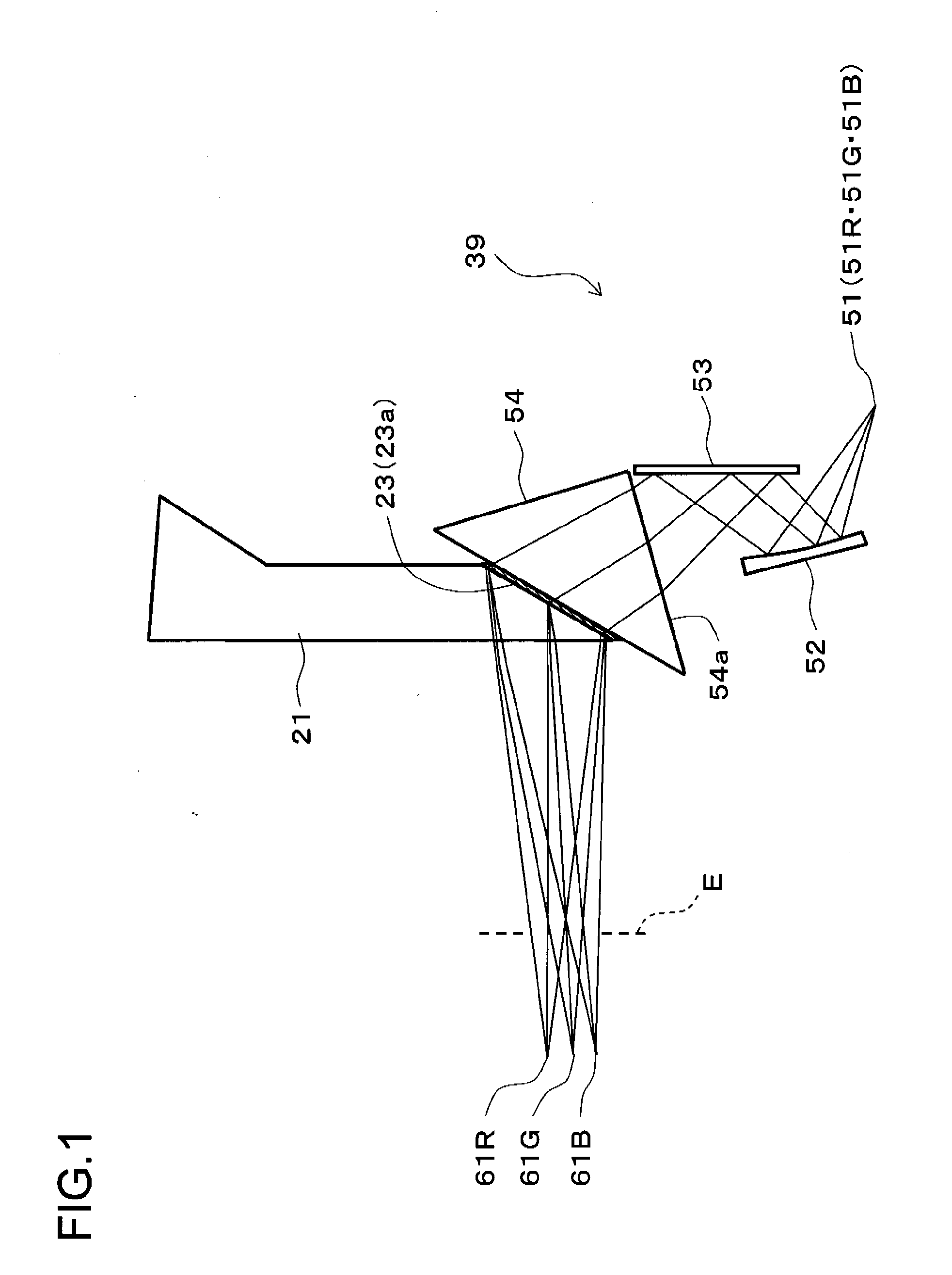
[0110]FIG. 11 is an illustrative diagram showing an outline of the overall construction of a fabrication optical system for a hologram optical element 23 according to this embodiment, and FIG. 12 is an illustrative diagram showing, with enlargement, a principal portion of this fabrication optical system. In this fabrication optical system, in place of the second condensing optical system 41 and the pinhole array 42 used in the first embodiment, there are arranged second condensing optical systems 41R, 41G, and 41B and pinholes 42R, 42G, and 42B. The pinholes 42R, 42G, and 42B are respectively arranged at the focus positions of the second condensing optica...

third embodiment

[0122]Yet another embodiment of the invention will be described below with reference to the relevant drawings. In the following description, for the sake of convenience of explanation, such members as find their counterparts in the first or second embodiment are identified by common reference signs and no overlapping description will be repeated.

[0123]FIG. 13 is an illustrative diagram showing an outline of the overall construction of a fabrication optical system for a hologram optical element 23 according to this embodiment. This fabrication optical system, compared with that of the first embodiment configured as shown in FIG. 5, further includes adjustment stages 70R, 70G, and 70B (an adjustment mechanism).

[0124]The adjustment stages 70R, 70G, and 70B are for adjusting the angles of reflection and positions of the reflecting mirrors 40R, 40G, and 40B (deflecting mirrors). More specifically, the adjustment stages 70R, 70G, and 70B are respectively composed of rotation stages 71R, 7...


PUM


Abstract

As a result of the light from a plurality of point light sources located at an identical position being refracted at a surface of a color correction prism at the time of exposure, the chromatic aberration occurring as a result of the light (for example, image light) directed via a refractive surface of the optical system used at the time of reconstruction to the viewer's pupil being refracted at this refractive surface is corrected for. Moreover, at least two of another set of a plurality of point light sources are arranged at such positions as to provide angles of incidence commensurate with the deviation between them of the ratio between exposure wavelength and use wavelength. Thus, even in a case where the ratio between exposure wavelength and use wavelength differs between at least two colors, it is possible to make equal for all colors the angle of diffraction that provides the maximum diffraction efficiency at the hologram optical element at the time of reconstruction, and thereby to correct for color shifting depending on the viewing angle.

Description

[0001]This application is based on Japanese Patent Application No. 2007-027580 filed on Feb. 7, 2007, the contents of which are hereby incorporated by reference.BACKGROUND OF THE INVENTION[0002]1. Field of the Invention[0003]The present invention relates to a method for fabricating a hologram optical element which involves exposing a hologram photosensitive material to two coherent light beams to thereby form a volume-phase reflection hologram optical element on a substrate. The invention also relates to a hologram optical element fabricated by that fabrication method, and to an image display apparatus employing such a hologram optical element.[0004]2. Description of Related Art[0005]There have conventionally been proposed various image display apparatuses in which, as shown in FIG. 14, a hologram optical element 102 is formed on a substrate 101 so that an image beam from a display element 103 is guided through the substrate 101 and is diffraction-reflected on the hologram optical e...

Claims


Application Information

Patent Timeline
Patent Type & Authority Applications(United States)
IPC IPC(8): G02B27/01G03H1/26G02B5/32
CPCG02B5/32G02B27/0172G02B2027/0109G02B2027/0116G02B2027/0174G03H1/0248G03H2222/18G03H1/26G03H1/2645G03H2001/0415G03H2001/0439G03H2001/266G03H1/0486
Inventor SHIMIZU, YOSHIEENDO, TAKESHI
Owner KONICA MINOLTA INC
Why Eureka
Try Eureka