Apparatus, system, and method for detecting the formation of a short between a magnetoresistive head and a head substrate

a technology of magnetoresistive head and substrate, applied in the field of magnetic tape drives, can solve problems such as reducing the bias voltage of the substra

Inactive Publication Date: 2008-08-07
IBM CORP
View PDF14 Cites 7 Cited by
  • Summary
  • Abstract
  • Description
  • Claims
  • Application Information

AI Technical Summary

Benefits of technology

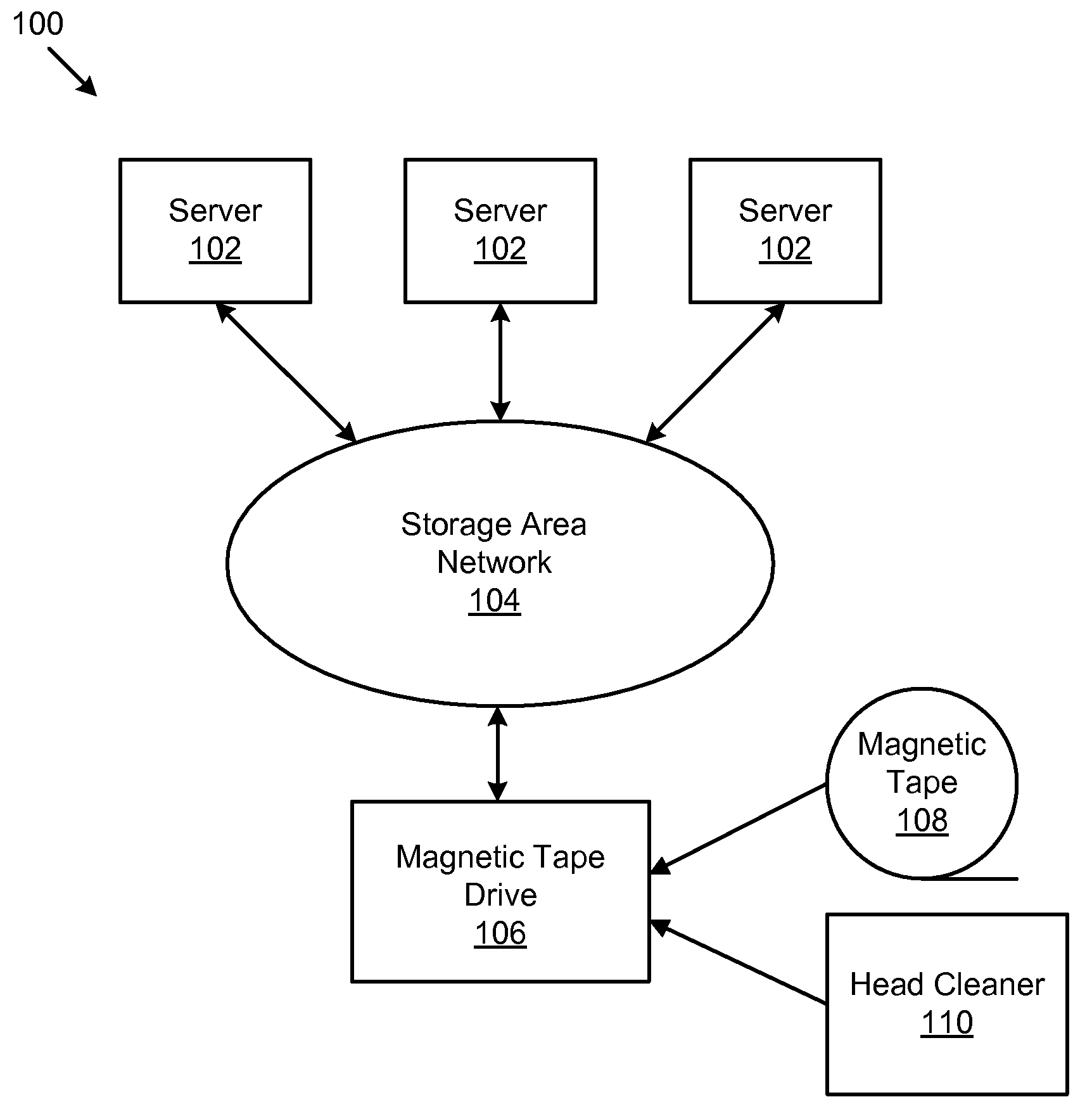
[0028]FIG. 5B is a simplified schematic circuit diagram illustrating one embodiment of a biasing circuit for generating a baseline electric potential level between a head substrate and ground;
[0029]FIG. 6 is a schematic flow chart diagram illustration on embodiment o

Problems solved by technology

The parallel combination is obviously less than the substrate voltage divide

Method used


Image

  • Apparatus, system, and method for detecting the formation of a short between a magnetoresistive head and a head substrate
  • Apparatus, system, and method for detecting the formation of a short between a magnetoresistive head and a head substrate
  • Apparatus, system, and method for detecting the formation of a short between a magnetoresistive head and a head substrate

Examples


Embodiment Construction

[0031]Many of the functional units described in this specification have been labeled as modules, in order to more particularly emphasize their implementation independence. For example, a module may be implemented as a hardware circuit comprising custom VLSI circuits or gate arrays, off-the-shelf semiconductors such as logic chips, transistors, or other discrete components. A module may also be implemented in programmable hardware devices such as field programmable gate arrays, programmable array logic, programmable logic devices or the like.

[0032]Modules may also be implemented in software for execution by various types of processors. An identified module of executable code may, for instance, comprise one or more physical or logical blocks of computer instructions which may, for instance, be organized as an object, procedure, or function. Nevertheless, the executables of an identified module need not be physically located together, but may comprise disparate instructions stored in d...


PUM


Abstract

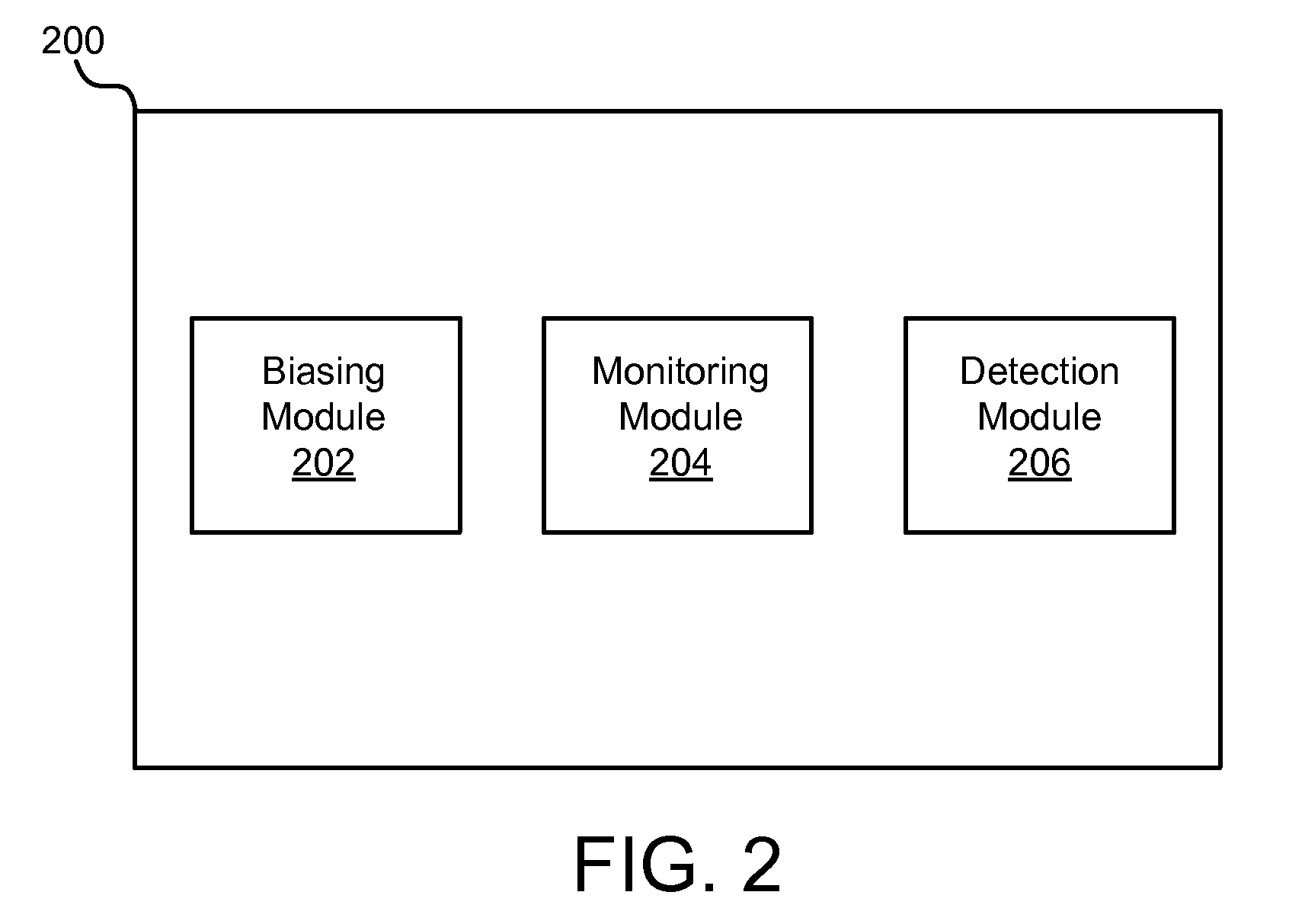
An apparatus, system, and method are disclosed for detecting the formation of a short between a magnetoresistive (“MR”) head and a head substrate. The apparatus is presented with a logic unit containing a plurality of modules configured to functionally execute the necessary steps of generating a baseline electric potential level between a head substrate and ground, monitoring the level of the electric potential between the head substrate and ground, and detecting the formation of a short circuit between the MR head and the head substrate by detecting a change in the electric potential level monitored by the monitoring module from the baseline level to a predetermined threshold level. Beneficially, such an apparatus, system, and method would reduce read errors on the magnetic tape storage system, the time and resources required to recover from such errors, and allow for preventative measures to obviate contamination short related failures of tape drive systems.

Description

BACKGROUND OF THE INVENTION[0001]1. Field of the Invention[0002]This invention relates to magnetic tape drives and more particularly relates to detecting the formation of a short between a magnetoresistive (“MR”) head and a head substrate.[0003]2. Description of the Related Art[0004]Prior to the advent of automation technology for linear tape drives, large, open tape reels were manually loaded by operators of tape storage systems. As advances in tape cassette and other technologies were adapted to magnetic tapes drives, large automated tape systems became possible. In such a system, magnetic tape cassettes are automatically selected from a library of tape cassettes, and loaded to and unloaded from magnetic tape drives by a robotic arm or other similar automation technology.[0005]The use of tape cassettes coincided with the introduction of magnetoresistive (MR) thin film heads, which are fabricated using processes similar to those used for hard disk drive heads. Both tape and hard di...

Claims


Application Information

Patent Timeline
IPC IPC(8): G11B5/33
CPCG11B5/3906G11B5/41G11B5/40
Inventor AXTMAN, BRIANBISKEBORN, ROBERT GLENNCZARNECKI, STANLEY W.TRETTER, LARRY LEEROY
Owner IBM CORP
Why Eureka
Try Eureka