In the process of networking based on network in different modes, because the
site selection for network equipment in different modes of networks is determined in accordance with the plan and optimization of network, there exists a situation that the
site selection for network equipment in network in different modes is inconsistent, which brings inconvenience to networking based on network in different modes.
However, as described above, the
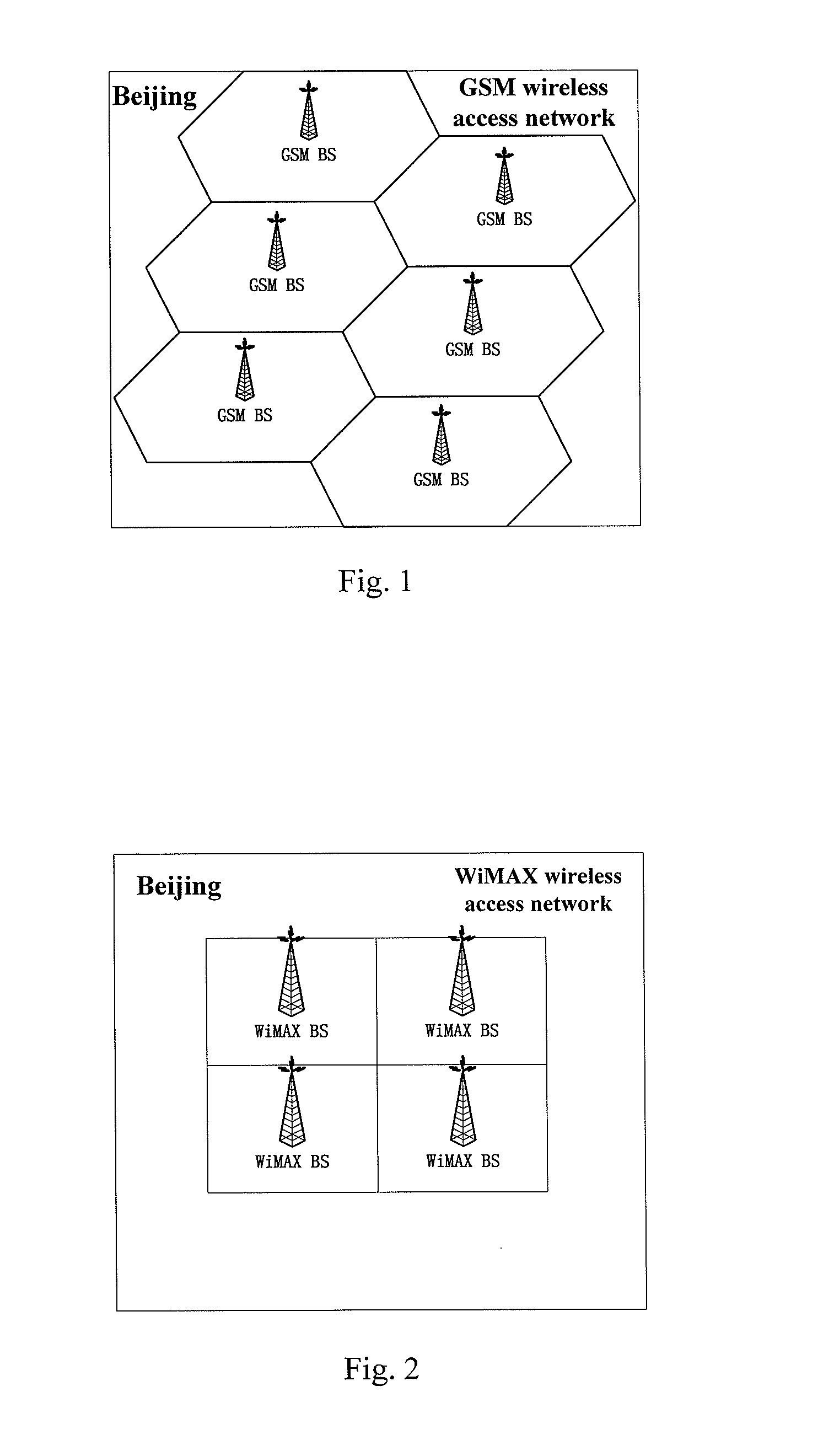
site selection for the original mode A wireless equipment is in conflict with that for the newly added mode B wireless
base station due to the difference between the plan of cellular networks in different modes.
It is a problem whether to perform the site selection in accordance with mode A
wireless network plan and place the upgraded multimode wireless integrated access equipment at the original site, or to perform another site selection in accordance with mode B
wireless network plan.
If the site selection is performed in accordance with mode B wireless network plan, it is an optimal site for mode B wireless
cellular network but not an optimal site for mode A wireless cellular network and furthermore operators need to take the land on lease and construct
machine rooms for the mode B wireless cellular network
base station and mode A wireless cellular network equipment.
Therefore, if cable resources of the mode A wireless cellular network and the mode B wireless cellular network can not be efficiently utilized by sharing, it is difficult to uniformly maintain the mode B wireless cellular network
base station and the mode A wireless cellular equipment, which may result in a high maintenance cost.
Because the site selection for equipment during the networking plan based on different modes of wired
access technology remains a problem, two wired access networks base on different modes of wired
access technology need to be constructed.
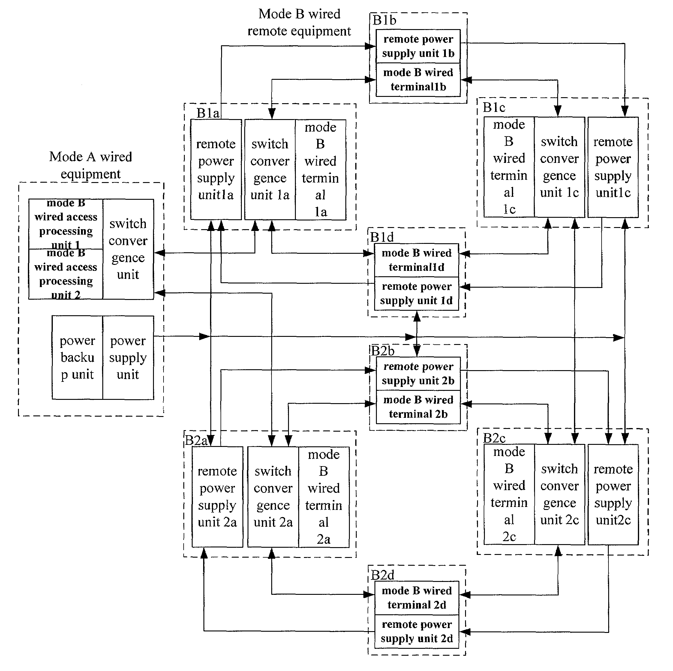
However, as described in FIG. 6, site selection for the original mode A wired equipment is in conflict with that for the newly added mode B wired equipment due to the difference between the plan of cellular networks in different modes.
If the site selection for the upgraded multimode wired integrated access equipment is performed in accordance with mode A wired
access network plan, it is an optimal site for mode A wired
access network but not an optimal site for mode B wired
access network.
Cable resources of the mode A wired access network and the mode B wired access network may not be efficiently utilized by sharing, and therefore it is difficult to uniformly maintain the mode B wired access equipment, which may result in a high maintenance cost.
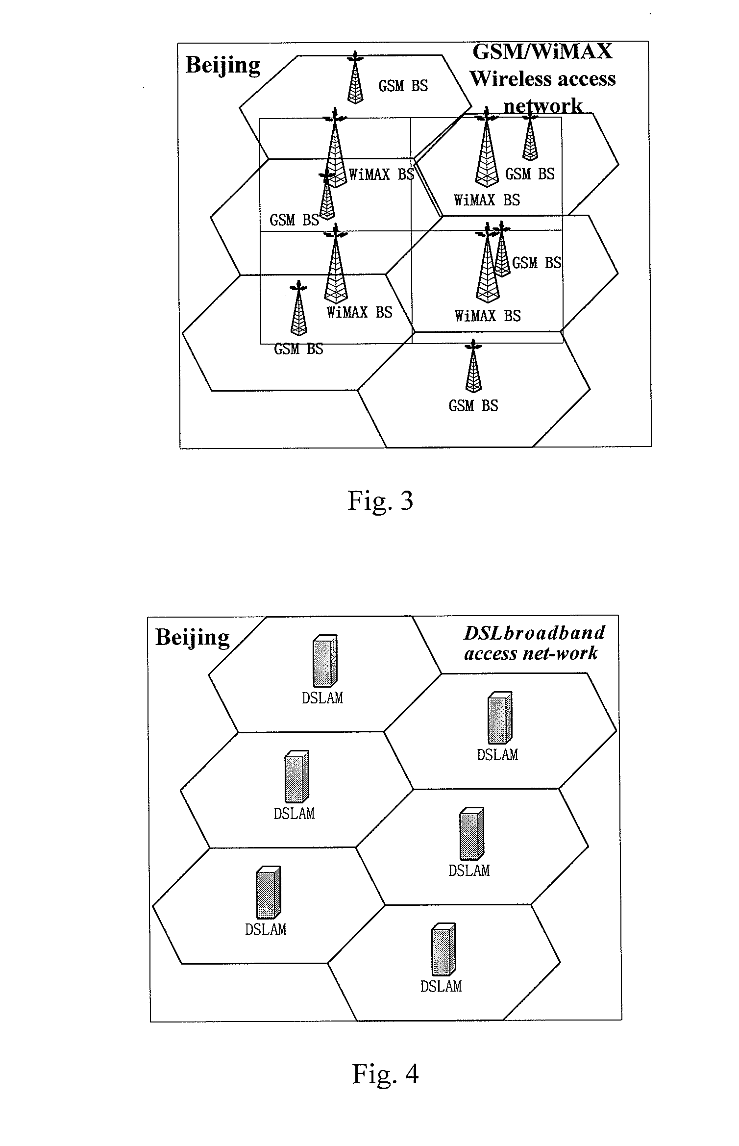
However, as described in FIG. 6, site selection for the original wireless equipment is in conflict with that for the newly added wired equipment due to the difference between the plan of wireless network and that of wired network.
If the site selection for the upgraded wireless and wired integrated access equipment is performed in accordance with wireless access network plan, it is an optimal site for wireless access network but not an optimal site for wired access network.
If the site selection is performed in accordance with wired access network plan, it is an optimal site for wired access network but not an optimal site for wireless access network.
The wired access network can not be constructed by upgrading the original wireless access network
If the wired access network can not be constructed by upgrading the original wireless access network, cable resources of wireless access network and the wired access network may not be efficiently utilized by sharing.
Therefore it is difficult to uniformly maintain the wired access equipment and wireless access equipment, which may result in a high maintenance cost.
Similarly, in the case of the existence of a wired access network, the same problem may exist if an access network based on wireless access mode is to be constructed.
In conclusion, for the multimode
network construction, there is no solution to the problem arising from the conflict of the site selection for equipment.


