
Fuel system for an aircraft including a fuel tank inerting system

a fuel system and aircraft technology, applied in the field of aircraft, can solve the problems of unable to eliminate the ignition source, thousands of aircraft lost due to enemy ground fire, and the complexity of the obiggs machin

Active Publication Date: 2008-08-07
THE BOEING CO
View PDF9 Cites 33 Cited by
  • Summary
  • Abstract
  • Description
  • Claims
  • Application Information

AI Technical Summary

Problems solved by technology

The military is well aware that when aircraft are operating in battlefield environments, eliminating ignition source is impossible.
During the Vietnam War, thousands of aircraft were lost due to enemy ground fire, from small arms fires to anti-aircraft artillery and surface-to-air missiles.
Analysis indicated that fuel tank fire and explosion was the major cause of aircraft due to ballistic impacts.
All of the above-identified systems have problems associated therewith.
Firstly, OBIGGS is a complex machine.
In addition, OBIGGS is an expensive addition to an aircraft.
Secondly, a passive system such as a bottled gas and dry ice would add significant logistics requirements to the aircraft.
However the foam is heavy; does not allow total use of available fuel in the tank; and deteriorates over time.
In addition replacing the foam in the fuel tank is messy and dangerous.

Method used


Image

  • Fuel system for an aircraft including a fuel tank inerting system
  • Fuel system for an aircraft including a fuel tank inerting system
  • Fuel system for an aircraft including a fuel tank inerting system

Examples


first embodiment

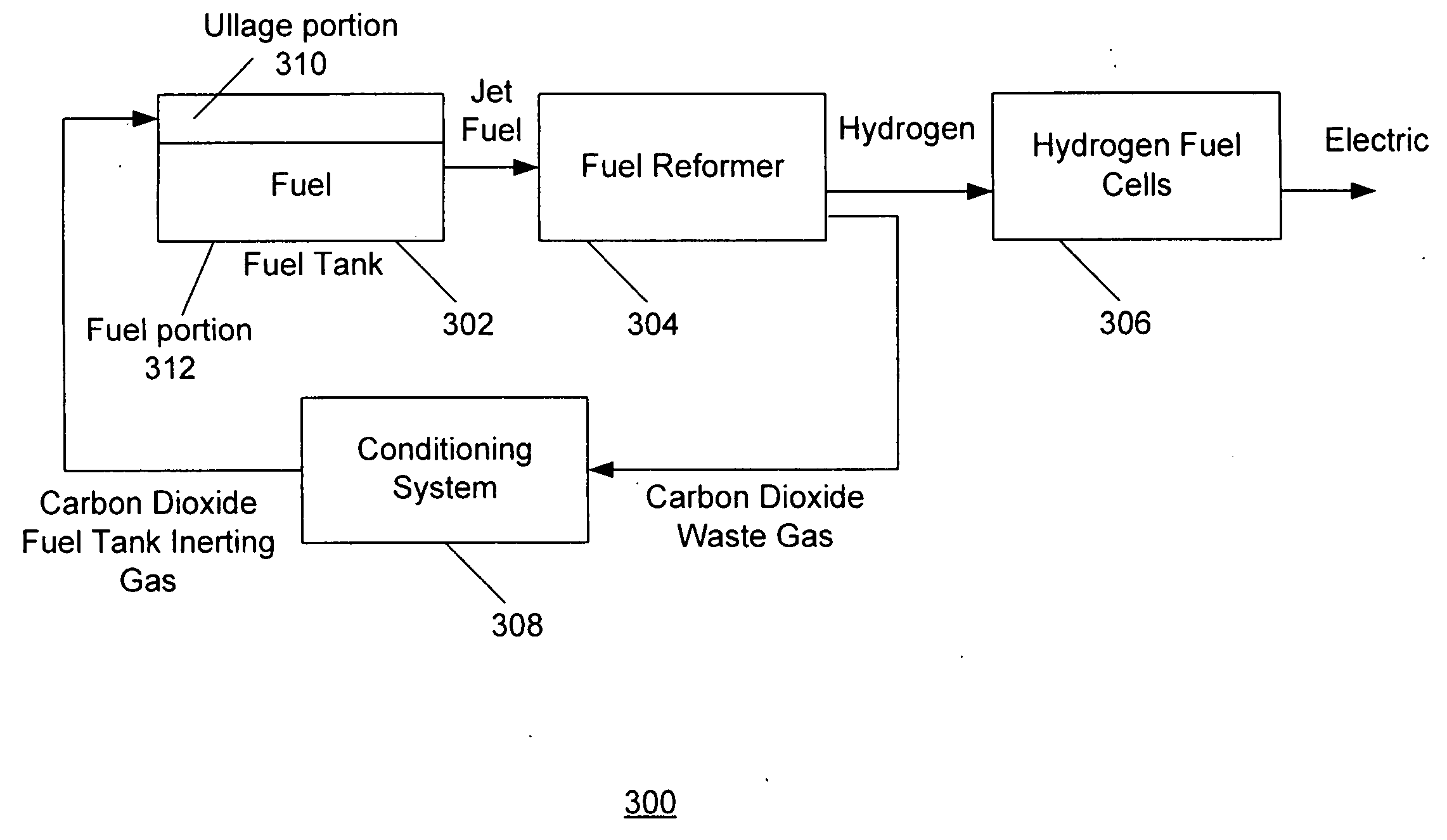
[0035]FIG. 4A is a block diagram of a fuel system for an aircraft including a fuel inerting system. As is seen, the fuel tank 302 may be coupled to the fuel reformer 304. The fuel tank 302 may include a fuel portion 312 and an ullage portion 310. Jet fuel may be transported from the fuel tank 302 to the fuel reformer 304. The fuel reformer may be coupled to hydrogen fuel cells 306. Hydrogen may be sent from the fuel reformer 304 to the hydrogen fuel cells 306. The hydrogen fuel cells 306 may then generate electric power for various components of a vehicle (e.g. aircraft).

[0036]Returning to the fuel reformer 304, the fuel reformer 304 may be also coupled to the conditioning system 308. An inerting waste gas may be provided from the fuel reformer 304 to the conditioning system 308. The conditioning system 308 may remove impurities in the waste gas to preserve the inerting properties. It should be understood that if the inerting gas (carbon dioxide) is pure, a conditioning system is no...

third embodiment

[0040]FIG. 4C is a block diagram of a fuel system for an aircraft including a fuel inerting system. Fuel tank 302″ may be coupled to fuel reformer 304″. The fuel tank 302″ may include a fuel portion 312″ and an ullage portion 310″. Jet fuel may be transported from the fuel tank 302″ to the fuel reformer 304″.

[0041]Fuel reformer 304″ may be coupled to the hydrogen fuel cells 306″. The hydrogen fuel cells 306″ may then generate electric power for various components of a vehicle (e.g. aircraft). The fuel reformer 304″ may provide inerting waste gas to the conditioning system 308″. The inerting waste gas may also be provided from the hydrogen fuel cells 306″ to the conditioning system 308″. The conditioning system 308″ may be coupled to the fuel tank 302″, and the inerting gas may be provided from the conditioning system 308″ to the fuel tank 302″. The conditioning system 308′ may have several elements including a water separator to remove water as one of the impurities. It should be un...


PUM


Abstract

A fuel system for an aircraft is disclosed. The fuel system comprises a fuel tank and a fuel reformer for receiving fuel from the fuel tank. The system includes a hydrogen fuel cell array for receiving hydrogen from the fuel reformer. The system further includes mechanism for providing an inerting gas from the fuel system to the fuel tank.

Description

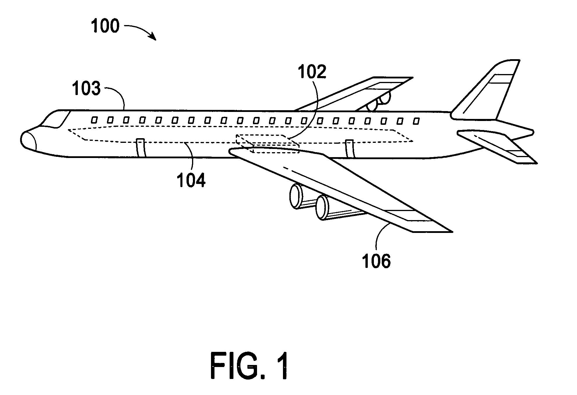
FIELD OF THE INVENTION[0001]The present embodiment relates generally to aircraft and more particularly to a fuel tank inerting system for use with the aircraft.BACKGROUND OF THE INVENTION[0002]Recent Federal Aviation regulations require that new transport aircraft include systems that provide for safe fuel tank operation. A flammable fuel mixture may occur as a function of the ullage portion of the fuel tank and environmental factors such as temperature and altitude.[0003]Three conditions are needed for ignition: a fuel, an oxidizer, and an ignition source. In a fuel tank, fuel is always present, ignition source and oxidizer may also be present. The Federal Aviation Administration (FAA) is working to eliminate ignition source in commercial aircraft fuel tanks. The military is well aware that when aircraft are operating in battlefield environments, eliminating ignition source is impossible. Both FAA and the military recognize reducing oxidizer in fuel tanks to below ignition limit is...

Claims


Application Information

Patent Timeline
IPC IPC(8): H01M8/04B65D90/44B64D37/32
CPCA62B7/14Y02T50/54A62C99/0018B64D37/005B64D37/32B64D41/00B64D2041/005H01M8/04208H01M8/0618H01M8/0662H01M2250/20Y02T50/545Y02T90/32Y02T90/36Y02E60/50A62C3/08Y02T50/50Y02T90/40A62C3/07H01M8/04
Inventor KWOK, DAVID W.
Owner THE BOEING CO
Learn More