Endoscope cleaning sheath, and endoscope apparatus and endoscope comprising the cleaning sheath
- Summary
- Abstract
- Description
- Claims
- Application Information
AI Technical Summary
Problems solved by technology
Method used
Image
Examples
first embodiment
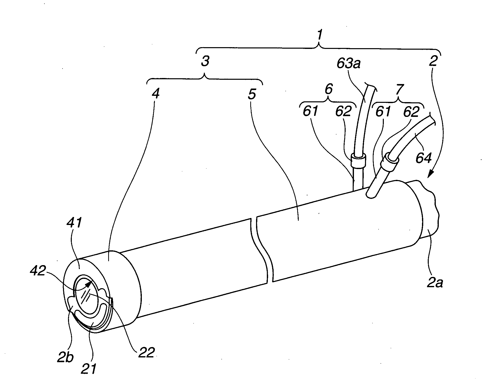
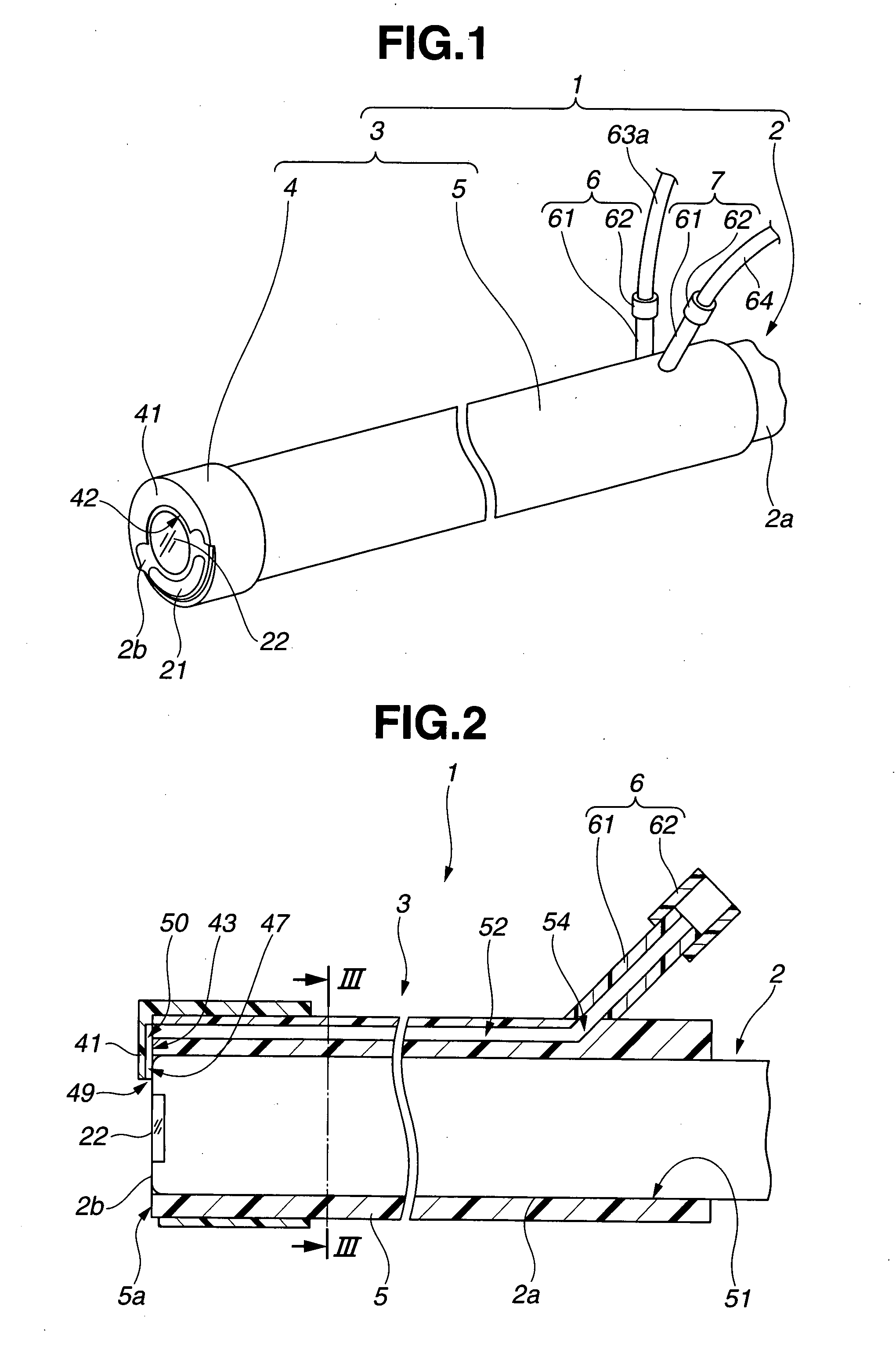
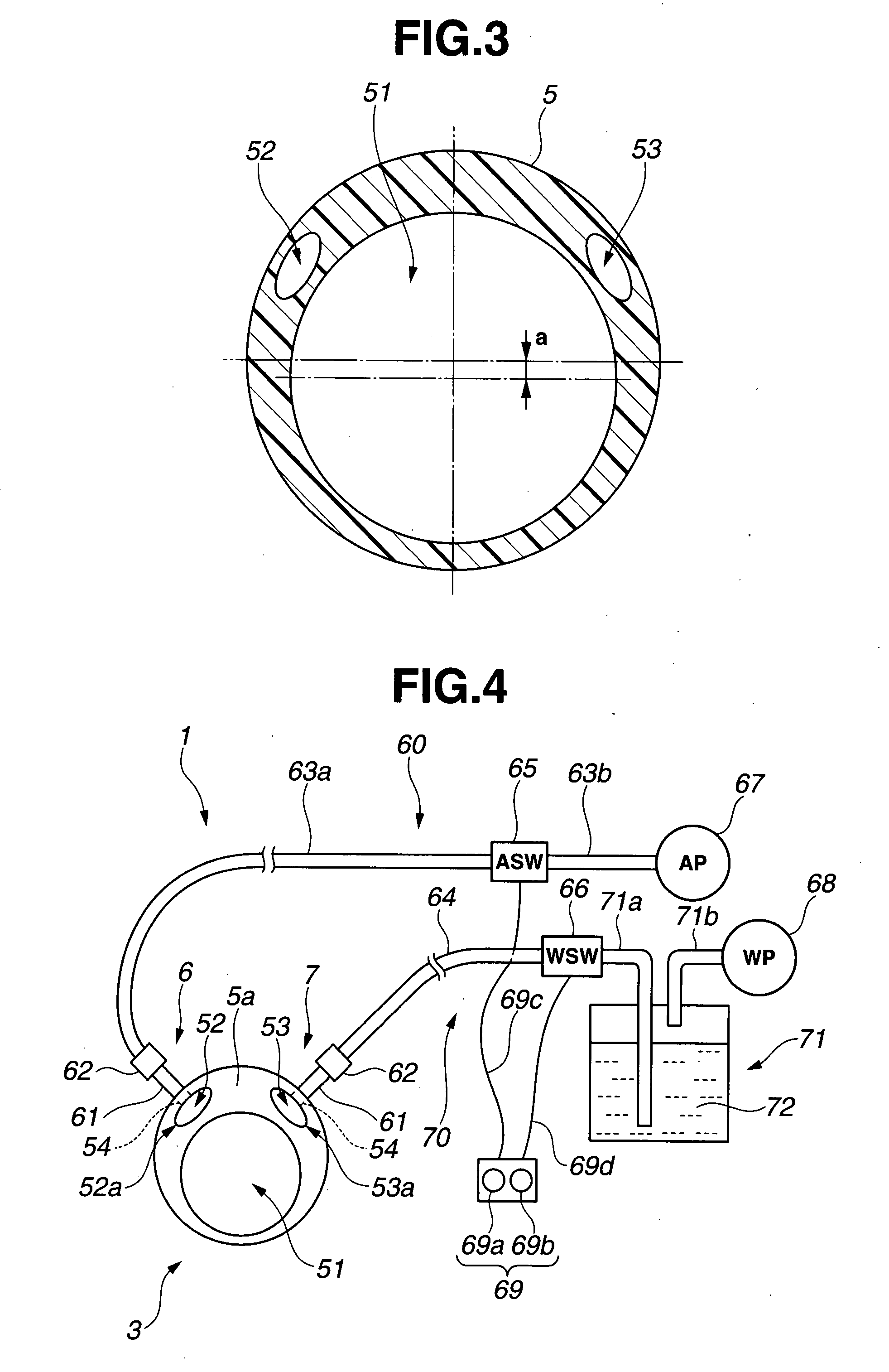
[0058]the endoscope apparatus comprising the endoscope cleaning sheath of the present invention will be described referring to FIG. 1 to FIG. 9.
[0059]As shown in FIG. 1, an endoscope apparatus 1 principally comprises an endoscope 2, an endoscope cleaning sheath 3, an air supply apparatus 60 that is described later, and a liquid supply apparatus 70 that is described later. The endoscope cleaning sheath 3 is attached to an insertion portion 2a of the endoscope 2, and is inserted into a body cavity in a manner in which it is integrated with the insertion portion2a.
[0060]In the endoscope 2, for example, the insertion portion 2a is a flexible and slender flexible mirror. At a distal end surface 2b of the insertion portion 2a are provided a light emitting end 21 of a light guide comprising an illumination optical system and an observation window 22 comprising an observation optical system.
[0061]The light incident end of the light guide is connected to an unshown light source. The observa...
second embodiment
[0105]the endoscope apparatus comprising the endoscope cleaning sheath according to the present invention will now be described referring to FIG. 10 to FIG. 18.
[0106]As shown in FIG. 10, an endoscope apparatus 1A according to the present embodiment comprises an air supply apparatus 60A and a liquid supply apparatus 70A for which an ejection state changeover switch 80 is provided as a control apparatus. The ejection state changeover switch 80 is provided instead of the air supply control switch 65 comprised by the air supply apparatus 60 and the liquid supply control switch 66 comprised by the liquid supply apparatus 70 according to the first embodiment.
[0107]The ejection state changeover switch 80 mainly comprises an apparatus main unit 81 and a switch portion 82. A switch groove 81a in which the switch portion 82 is disposed is formed in the apparatus main unit 81. For this reason, an upper as shown in the figure of the apparatus main unit 81 is divided into a one-side surface port...
third embodiment
[0154]the endoscope apparatus will now be described referring to FIG. 28 to FIG. 37.
[0155]An endoscope apparatus 1B according to the present embodiment as shown in FIG. 28 comprises a tube body 5B in place of the tube body 5 of the first embodiment. It also comprises an ejection state changeover switch 80B instead of the ejection state changeover switch 80. Furthermore, according to the present embodiment, air that is supplied from the air supply pump 67 is supplied to the second air supply tube 63b and a fourth air supply tube 63d, respectively, through a branching device 90. Accordingly, the air supply apparatus 60B comprises the air supply pump 67, the branching device 90, the air supply tubes 63a, 63b, 63c and 63d, and the ejection state changeover switch 80B.
[0156]First, the configuration of the tube body 5B will be described.
[0157]The tube body 5B comprises, for example, four holes 51, 52b, 52c, and 53. More specifically, the tube body 5B comprises a first air supply hole 52b,...
PUM
 Abstract
Description
Claims
Application Information
 - R&D
- Intellectual Property
- Life Sciences
- Materials
- Tech Scout
- Unparalleled Data Quality
- Higher Quality Content
- 60% Fewer Hallucinations
Browse by: Latest US Patents, China's latest patents, Technical Efficacy Thesaurus, Application Domain, Technology Topic, Popular Technical Reports.
© 2025 PatSnap. All rights reserved.Legal|Privacy policy|Modern Slavery Act Transparency Statement|Sitemap|About US| Contact US: help@patsnap.com


