
Pump Assembly With Safety Valve

a safety valve and pump technology, applied in the direction of positive displacement liquid engines, suction devices, needles, etc., can solve the problems of drug thereby unintentionally infused into the patient, the flexible reservoir is compressed, and the initial cost of such a pump, and achieves a high degree of protection

Inactive Publication Date: 2008-08-07
NOVO NORDISK AS
View PDF29 Cites 51 Cited by
  • Summary
  • Abstract
  • Description
  • Claims
  • Application Information

AI Technical Summary

Benefits of technology

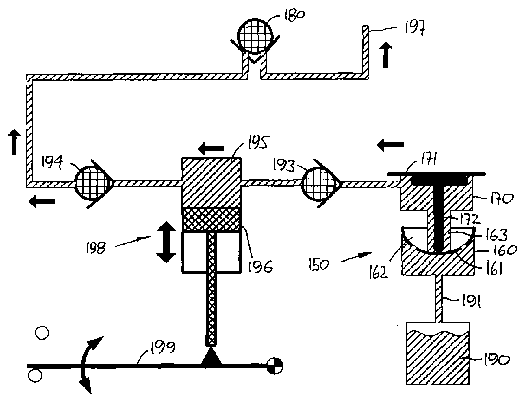
[0016]The suction pump may be of any desirable type, e.g. it may comprise a variable-volume pump chamber and an inlet respectively an outlet valve associated with the pump inlet respectively the pump outlet. The inlet and the outlet valves may be controlled by pressure generated in the pump chamber, e.g. in the form of membrane valves. The pump may also be in the form of a roller pump although this type of pump due to its compressed tubing normally provides a high degree of protection against undesired flow of fluid through the pump generated by outside pressure.
[0017]In case a relative vacuum arises at the fluid outlet (as may arise in a patient), fluid may be sucked through the valves of the pump assembly and e.g. into the patient. To prevent such a situation, the pump assembly may further comprise a second safety valve arranged in the fluid communication between the pump outlet and the fluid outlet, the second safety valve allowing fluid to move from the pump outlet to the fluid outlet, yet prevents fluid from being sucked through the pump assembly and into a patient.

Problems solved by technology

The first class comprises infusion pumps which are relatively expensive pumps intended for 3-4 years use, for which reason the initial cost for such a pump often is a barrier to this type of therapy.
However, when a flexible reservoir is compressed from the outside the contained drug may be expelled through the outlet and into the patient.
Although such a flexible reservoir normally will be protected by a relatively rigid housing, the housing may brake when subjected to excessive force, this allowing the flexible reservoir to be compressed and drug thereby unintentionally infused into the patient.

Method used


Image

  • Pump Assembly With Safety Valve
  • Pump Assembly With Safety Valve
  • Pump Assembly With Safety Valve

Examples


Embodiment Construction

[0052]When in the following terms such as “upper” and “lower”, “right” and “left”, “horizontal” and “vertical” or similar relative expressions are used, these only refer to the appended figures and not to an actual situation of use. The shown figures are schematic representations for which reason the configuration of the different structures as well as there relative dimensions are intended to serve illustrative purposes only.

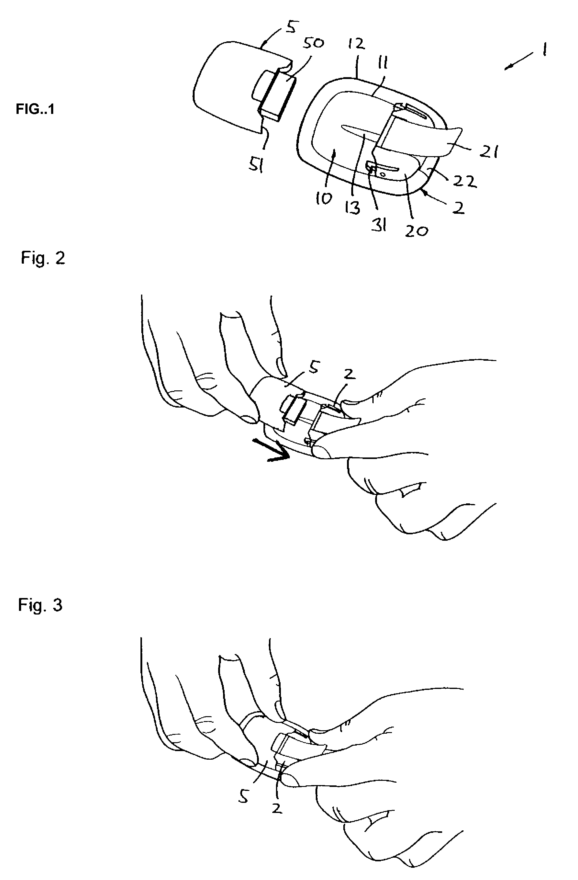
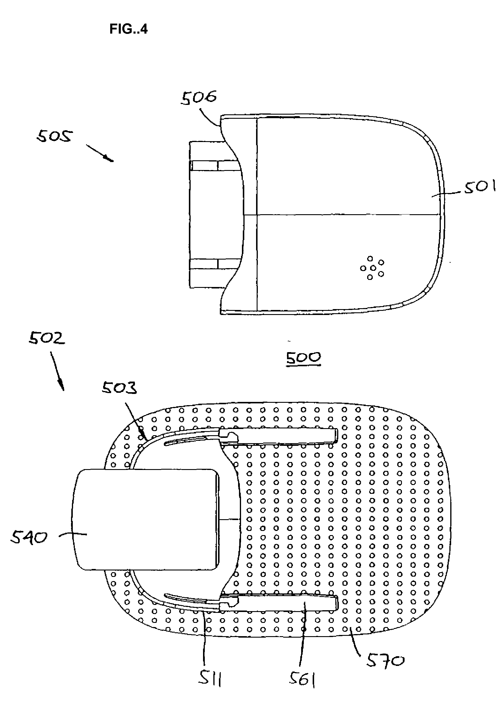
[0053]Before turning to the present invention per se, a system suitable to be used in combination therewith will be described, the system comprising a pump unit, a patch unit adapted to be used in combination with the pump unit, and a remote control unit for wireless communication with the pump unit. However, the present invention may be used in any system or unit in which the features of the present invention would be relevant, e.g. in a conventional durable infusion pump or system.

[0054]Firstly, with reference to FIGS. 1-3 an embodiment of a medical device fo...


PUM


Abstract

The invention provides a pump assembly comprising a suction pump and a safety valve arranged between the pump inlet and a fluid inlet for the assembly. The safety valve comprises an inlet valve and a moveable control member acting on the safety inlet valve, wherein the control member is operatable between an initial position in which the safety inlet valve is closed, and an activated position in which the safety inlet valve is open, and wherein the control member is moved from the initial to the activated position by means of suction action from the pump. By this arrangement the opening of the safety valve is positively controlled by the suction provided by the pump whereas the safety valve is closed during non-operation of the pump.

Description

[0001]The present invention generally relates to a pump assembly comprising a safety valve adapted to prevent unintended flow of fluid through the pump assembly.BACKGROUND OF THE INVENTION[0002]In the disclosure of the present invention reference is mostly made to the treatment of diabetes by injection or infusion of insulin, however, this is only an exemplary use of the present invention.[0003]Portable drug delivery devices for delivering a drug to a patient are well known and generally comprise a reservoir adapted to contain a liquid drug and having an outlet in fluid communication with a hollow infusion needle, as well as expelling means for expelling a drug out of the reservoir and through the skin of the subject via the hollow needle. Such devices are often termed infusion pumps.[0004]Basically, infusion pumps can be divided into two classes. The first class comprises infusion pumps which are relatively expensive pumps intended for 3-4 years use, for which reason the initial co...

Claims


Application Information

Patent Timeline
Patent Type & Authority Applications(United States)
IPC IPC(8): A61M5/142A61M5/145A61M1/00F04B19/04F04B19/00F04B19/22
CPCA61M5/1413A61M5/14216A61M5/14248A61M39/24A61M2005/14252A61M2039/2433A61M2005/14264A61M2005/14268A61M2005/1581A61M2005/1585A61M2039/242A61M2005/1426
Inventor LARSEN, BJORN GULLAKHANSEN, STEFFENGLEJBOL, KRISTIANMOLLER-JENSEN, PETERTOFT, TUEHVID, NIELSLARSEN, PREBEN
Owner NOVO NORDISK AS
Learn More