
Vascular image extraction and labeling system and method

a technology of vascular image and labeling system, applied in the field of medical imaging, can solve the problems of affecting the usefulness of imaging technologies, relative difficulty in discerning a particular structure of interest from its background, and the possibility of still existential problems in identifying an anatomical featur

Active Publication Date: 2008-08-07
GENERAL ELECTRIC CO
View PDF7 Cites 71 Cited by
  • Summary
  • Abstract
  • Description
  • Claims
  • Application Information

AI Technical Summary

Problems solved by technology

One factor that can impair the usefulness of these imaging technologies is the relative difficulty in discerning a particular structure of interest from its background, especially when the background has a similar texture or structure.
In some applications, problems in identifying an anatomical feature may still exist after segmentation.
However, the large number of blood vessels remaining after segmentation makes identifying a specific blood vessel difficult.
In addition, the blood vessels of the brain make many twists and turns, as well as intertwine, making it even more difficult to identify a specific blood vessel.
As a result, it may be difficult to identify or track an individual blood vessel as it courses its way around the brain.
However, a normal segmented image of the blood vessels of the brain may not be particularly helpful in either situation.
It may be difficult for the radiologist to identify the specific blood vessel involved.
Furthermore, it may be difficult to distinguish a bifurcation point in a blood vessel from simply the overlapping of two blood vessels.

Method used


Image

  • Vascular image extraction and labeling system and method
  • Vascular image extraction and labeling system and method
  • Vascular image extraction and labeling system and method

Examples


Embodiment Construction

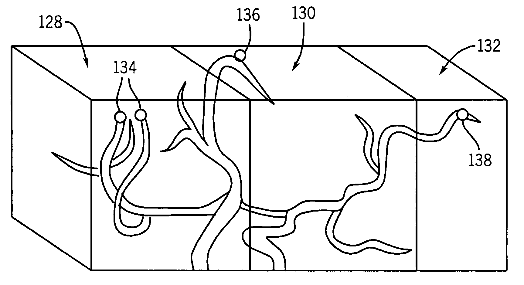
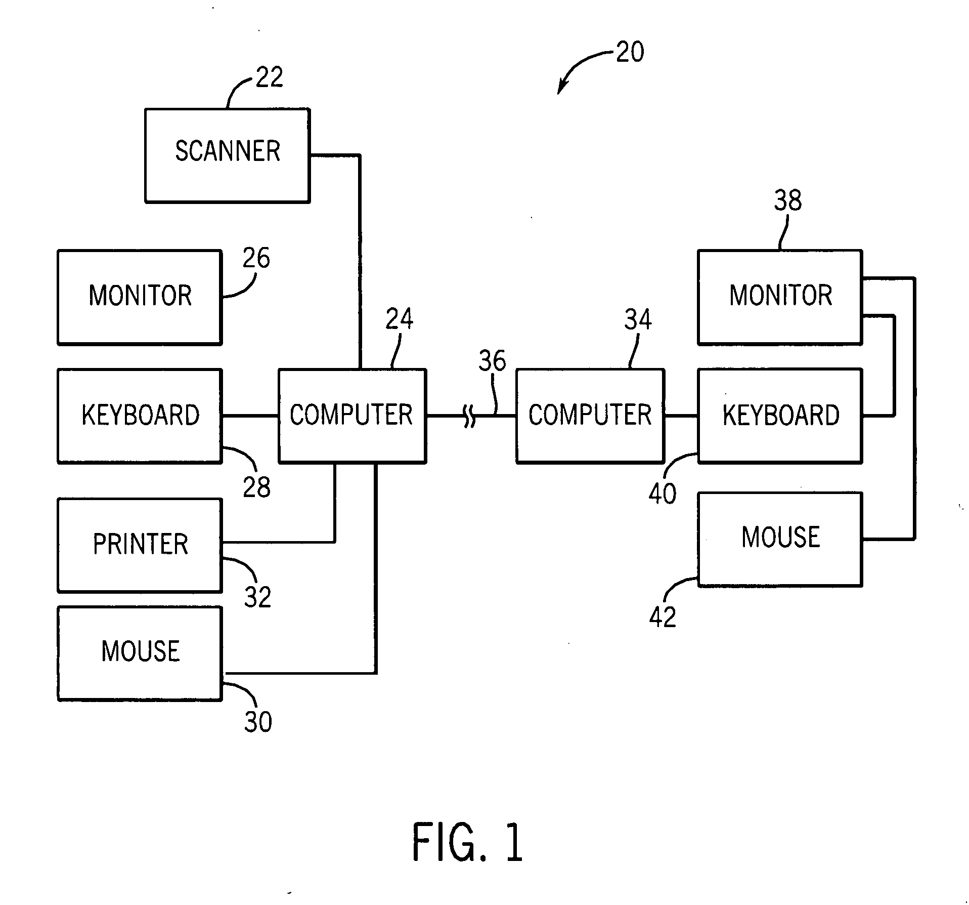
[0017]Referring generally to FIG. 1, a diagrammatical view of a medical imaging system 20 having a scanner 22 that is operable to scan a patient in three-dimensions and to produce medical image data of the internal anatomy of a patient is provided. The scanner 22 may utilize any of a variety of different imaging modalities, such as Computed Tomography (CT), Magnetic Resonance (MR), or Positron Emission Tomography (PET). In this embodiment, the medical image data obtained by the scanner 22 is in a digital form. Three-dimensional images are comprised of voxels. A voxel in three-dimensional medical imaging is analogous to a pixel in two-dimensional imaging. A voxel is a volume element represents a value in a grid in three-dimensional space. The scanner 22 is operable to assign values to the voxels. The value of a voxel may represent various properties. In CT scans, the values are Hounsfeld units that represent the opacity of material to X-rays. In MR imaging, the voxels represent a dif...


PUM


Abstract

A technique for producing a three-dimensional segmented image of blood vessels and automatically labeling the blood vessels. A scanned image of the head is obtained and an algorithm is used to segment the blood vessel image data from the image data of other tissues in the image. An algorithm is used to partition the blood vessel image data into sub-volumes that are then used to designate the root ends and the endpoints of major arteries. An algorithm is used to identify a seed-point voxel in one of the blood vessels within one of the sub-volume of the partition. Other voxels are then coded based on their geodesic distance from the seed-point voxel. An algorithm is used to identify endpoints of the arteries. This algorithm may also be used in the other sub-volumes to locate the starting points and endpoints of other blood vessels. One sub-volume is further sub-divided into left and right, anterior, medial, and posterior zones. Based on their location in one of these zones, the voxels corresponding to the endpoints of the blood vessels are labeled. Starting from these endpoints, the artery segments are tracked back to their starting points using an algorithm that simultaneously labels all of the blood vessel voxels along the path with a corresponding anatomical label identifying the blood vessel to which it belongs.

Description

BACKGROUND[0001]The invention relates generally to the field of medical imaging. More particularly, the present invention relates to a technique for automatically identifying and labeling blood vessels in a medical image.[0002]Volumetric medical imaging systems have become a valuable tool in the diagnosis and treatment of many illnesses and diseases. As opposed to conventional X-ray imaging systems that are only able to gather only two-dimensional information about a patient's internal anatomical features, volumetric medical imaging systems are able to gather internal anatomical information in three-dimensions. This three-dimensional information can then be used to form medical images from a variety of different perspectives, whereas conventional X-ray images are limited to an image from a single view. Examples of volumetric imaging systems are Computed Tomography (CT) imaging systems, Magnetic Resonance Imaging (MRI) systems, and Positron Emission Tomography (PET).[0003]One factor ...

Claims


Application Information

Patent Timeline
Patent Type & Authority Applications(United States)
IPC IPC(8): G05B19/42
CPCG06K9/4638G06K2209/05G06T7/0081A61B6/506G06T2207/10072G06T2207/30101G06T7/0093G06T7/11G06T7/162G06V10/457G06V2201/03A61B6/00A61B5/00
Inventor SURYANARAYANAN, SRIKANTHMALLYA, YOGISHASHRIRAM, KRISHNA SEETHARAMGOPINATH, AJAYJOSHI, MUKTA C.
Owner GENERAL ELECTRIC CO
Features
  • Generate Ideas
  • Intellectual Property
  • Life Sciences
  • Materials
  • Tech Scout
  • Unparalleled Data Quality
  • Higher Quality Content
  • 60% Fewer Hallucinations
Learn More