Network system which performs peer-to-peer communication

a peer-to-peer communication and network system technology, applied in the field of network systems, can solve the problems of insufficient communication source terminals, inefficient conduct, heavy load on the network, etc., and achieve the effect of improving the efficiency of peer-to-peer communication and lightening the load on the network

Inactive Publication Date: 2008-08-07
HITACHI LTD
View PDF9 Cites 18 Cited by
  • Summary
  • Abstract
  • Description
  • Claims
  • Application Information

AI Technical Summary

Benefits of technology

[0028]According to the present invention, the load inflicted on a network by secure peer-to-peer communication between terminals can be lightened. The present invention also makes peer-to-peer communication possible despite path control, and improves the efficiency of peer-to-peer communication in a community where the same members are likely to communicate with each other more than once.

Problems solved by technology

A first problem is that the load on the network is heavy when too many terminals simultaneously participate in negotiation of secure communication parameters for secure peer-to-peer communication between terminals.
Since discussed herein is communication within a community and the same community members communicate with each other more than once, it is inefficient to conduct the negotiation each time, which constitutes a second problem.
Then the location information of the communication destination terminal obtained by the communication source terminal with the use of peer-to-peer network technology is not enough to enable the communication source terminal to access the communication destination terminal.
The terminals therefore cannot establish peer-to-peer communication, which constitutes a third problem.

Method used


Image

  • Network system which performs peer-to-peer communication
  • Network system which performs peer-to-peer communication
  • Network system which performs peer-to-peer communication

Examples


first embodiment

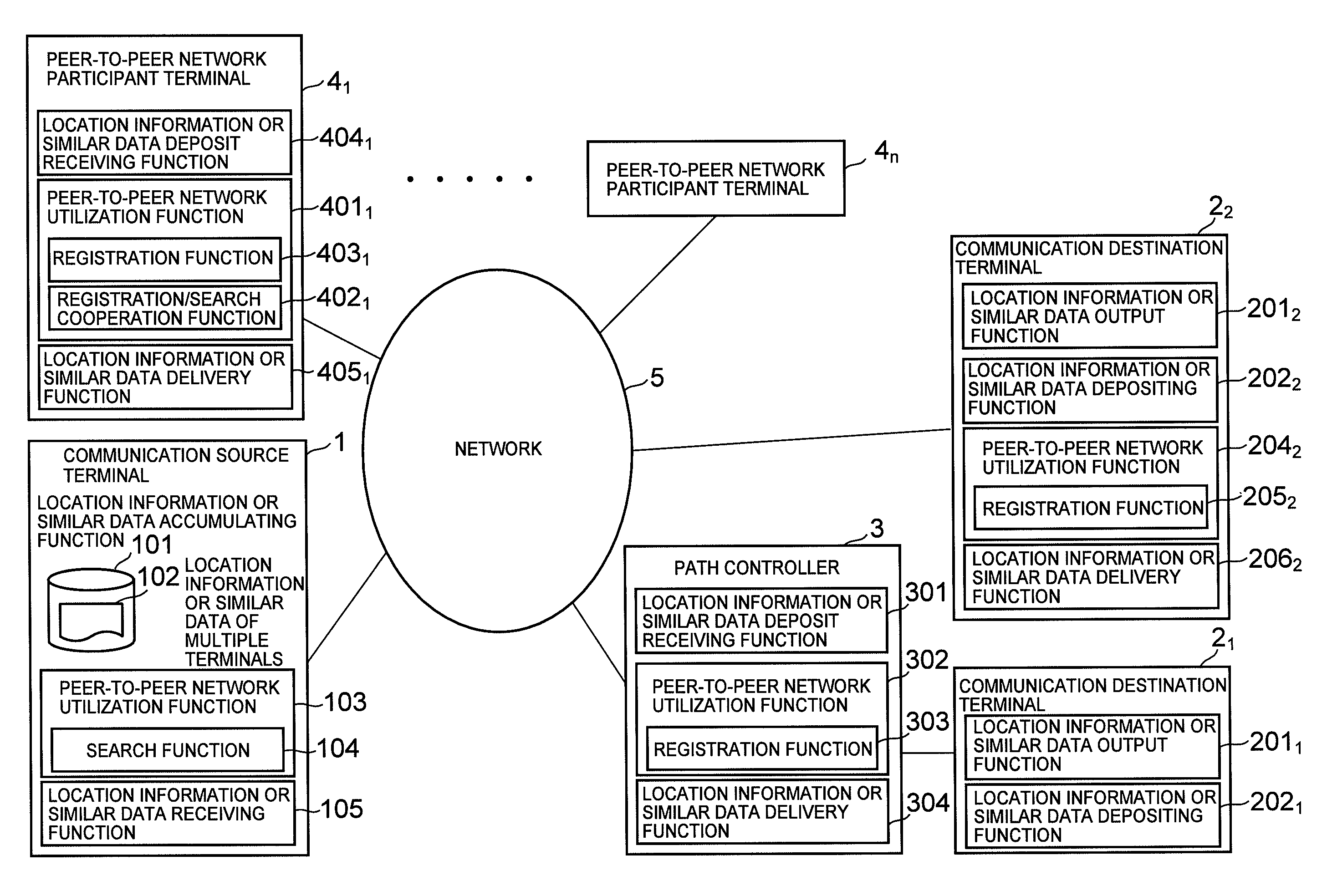
[0060]FIG. 3 shows a configuration example of an embodiment of the present invention in which users of terminals located in different corporations form a cross-company group to communicate audio data, exchange documents, or the like through peer-to-peer communication held between members of the group over a network.

[0061]In this embodiment, the method using DHT is employed as peer-to-peer network technology.

[0062]The terminals operated by the group members can utilize the method using DHT. A terminal that is operated by a member a of the group is connected to a company A internal network 61. A terminal that is operated by a member b of the group is coupled to a company B internal network 62. A terminal that is operated by a member c of the group is coupled to an external network 5. Terminals operated by the rest of the members of the group are individually coupled to the external network 5, the company A internal network 61, the company B internal network 62, or an internal network ...

second embodiment

[0134]FIG. 10 shows a configuration example of an embodiment of the present invention in which multiple households form a group to exchange video data, audio data, and the like created in the respective households through peer-to-peer communication held between members of the group with the use of a DVD player, a PC, or other picture reproducing machine that is coupled to a network.

[0135]This embodiment employs the “inter-group cooperation method” as peer-to-peer network technology.

[0136]The configuration of FIG. 10 has multiple picture reproducing machines that can utilize the “inter-group cooperation method” and reproduces images and sounds. The picture reproducing machines are coupled to the external network 5.

[0137]A picture reproducing machine that is operated by a user a is the communication source terminal 1 and a picture reproducing machine that is operated by a user b is the communication destination terminal 2. The rest of the picture reproducing machines are the peer-to-p...


PUM


Abstract

To reduce a load inflicted on a network by peer-to-peer communication between terminals, the present invention provides a network system having a communication destination machine and a communication source machine, in which: the communication destination machine includes a unit which registers its own location information in a peer-to-peer network; and the communication source machine includes: a unit which searches the peer-to-peer network for the location information of the communication destination machine and obtains the location information; and a unit which uses the obtained information to establish peer-to-peer communication. The location information contains communication path information which enables the communication source machine to communicate with a desired machine beyond a path controller, and a parameter necessary for communication. The communication source machine may include a unit which accumulates location information or similar data of multiple communication destination machines.

Description

INCORPORATION BY REFERENCE[0001]This application claims priority based on a Japanese patent application, No. 2007-013546 filed on Jan. 24, 2007, the entire contents of which are incorporated herein by reference.BACKGROUND OF THE INVENTION[0002]The present invention relates to a network system capable of secure peer-to-peer communication among multiple information terminals coupled to a network.[0003]As the Internet becomes common and the communication line speed grows faster, an increasing demand has been created for exchange of information through peer-to-peer communication between a personal computer (PC) or a terminal with a telephone function and another PC or terminal with a telephone function on a remote site over a network.[0004]To establish communication between terminals over a network, a communication source terminal which initiates a communication session needs to have the IP address or other location information of a communication destination terminal which is on the oth...

Claims


Application Information

Patent Timeline
Patent Type & Authority Applications(United States)
IPC IPC(8): G06F15/16G06F21/00G06F21/44
CPCH04L63/0823H04L67/1065H04L67/104H04L67/51
Inventor NEMOTO, SHIGEYUKIFUJISHIRO, TAKAHIROKAWANO, AYUMIMORITA, KEIJI
Owner HITACHI LTD
Why Eureka
Try Eureka