
Railcar for passenger transport

a passenger transport and railcar technology, applied in the direction of carriages, wagons/vans, locomotives, etc., can solve the problems of consequently the energy consumption of the railcar, reducing the passenger capacity of the architecture, and a large number of bogies also requiring numerous maintenance operations, so as to achieve the effect of reducing maintenance operations, increasing the energy consumption of the vehicle, and increasing the resistance to forward movemen

Inactive Publication Date: 2008-08-14
ALSTOM TRANSPORT SA
View PDF3 Cites 18 Cited by
  • Summary
  • Abstract
  • Description
  • Claims
  • Application Information

AI Technical Summary

Benefits of technology

[0044]One advantage of an architecture which is completely articulated is that the railcar is more stable in the event of derailment. Owing to the articulated architecture, the resistance to forward movement and therefore the energy consumption required to drive the vehicle remains limited compared with a non-articulated railcar of the same length, since there are fewer bogies. The maintenance operations are also reduced. Owing to the railcar composition, the vehicle provides a large capacity since the entire length of the vehicle is used to receive passengers.
[0045]One advantage of the concentration of traction drives in the driving carriages and in a single motorised intermediate carriage allows better protection from and control of fires by physically separating the traction drives from each other and by physically separating the traction drives from the passenger compartments.

Problems solved by technology

Owing to the non-articulation, this architecture has the disadvantage of having a large number of bogies which increases the resistance to forward movement and consequently the energy consumption of the railcar.
A large number of bogies also requires numerous maintenance operations.
This architecture has a reduced passenger capacity compared with a railcar having an identical length since the motor cars are not accessible to passengers.
The efficiency levels of these vehicles are linked to the architectures thereof: it is possible to cause a high-speed train to travel at lower speeds, but at the expense of passenger capacity since the mass of traction drives cannot be released.
It is not possible to cause a vehicle to travel at a higher speed than its maximum speed since a traction drive or a motor cannot simply be added.

Method used


Image

  • Railcar for passenger transport
  • Railcar for passenger transport
  • Railcar for passenger transport

Examples


first embodiment

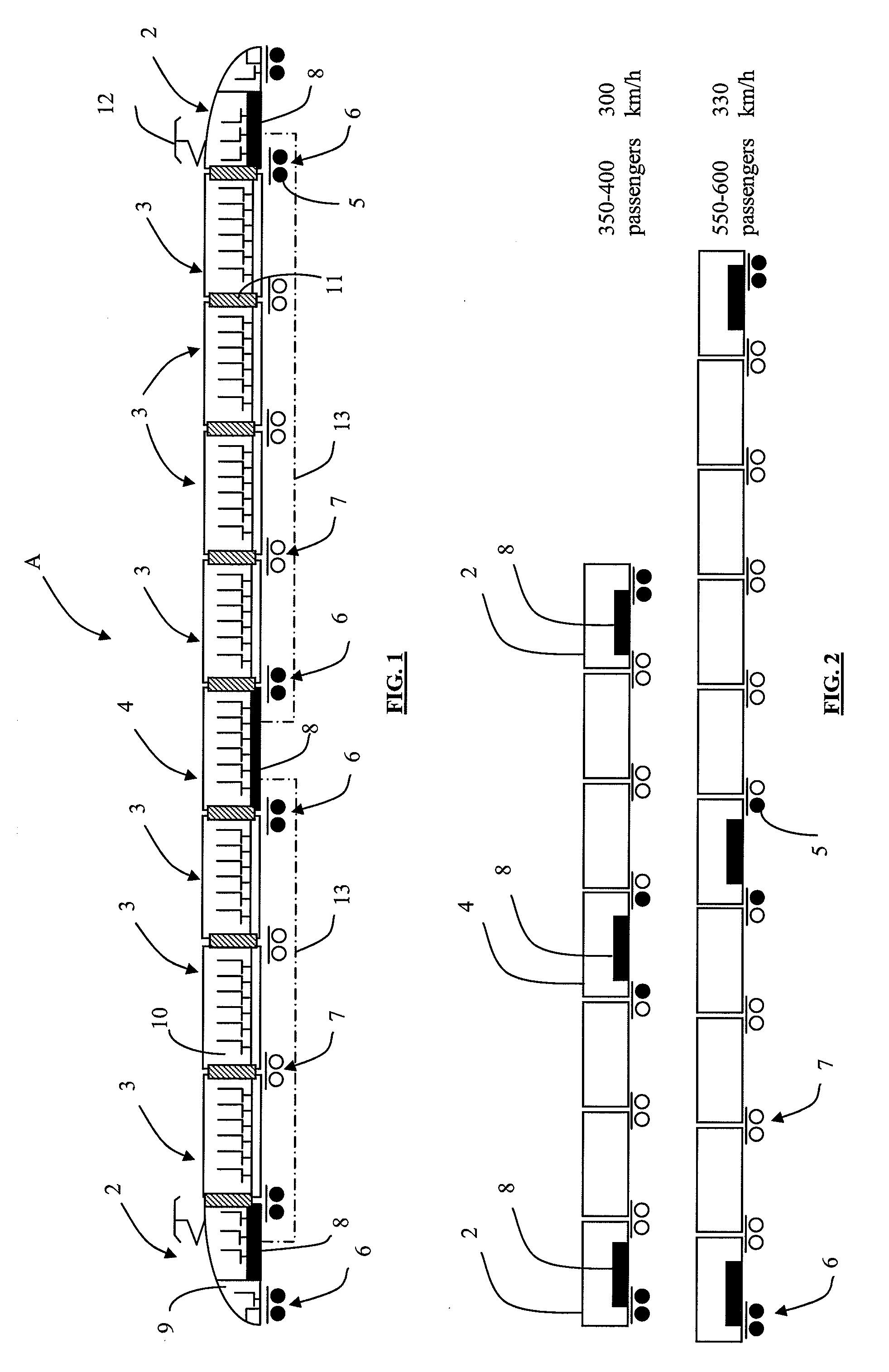
[0050]As illustrated in FIG. 1, a railcar A comprises seven trailers 3 and a motorised intermediate carriage 4 which are arranged between two driving carriages 2.

[0051]A first driving carriage 2 is located at a first end of the railcar A (from the left-hand side in FIG. 1). It has a free end, where a driver's cabin 9 is located, and rests on a motor bogie 6 which is composed of two motor axles 5. A first traction drive 8 is arranged below the passenger compartment 10 of this first driving carriage 2. At the opposite end thereof, the driving carriage 2 is articulated to a first trailer 3. The two ends facing the carriages 2 and 3 rest on a single motor bogie 6 which is composed of two motor axles 5.

[0052]The first trailer 3 therefore shares, at the first end thereof, a motor bogie 6 with the driving carriage 2 and shares, at the other end thereof, a carrier bogie 7 with the second adjacent trailer 3.

[0053]The second trailer 3 is articulated to the first trailer 3 and to the third tra...

second embodiment

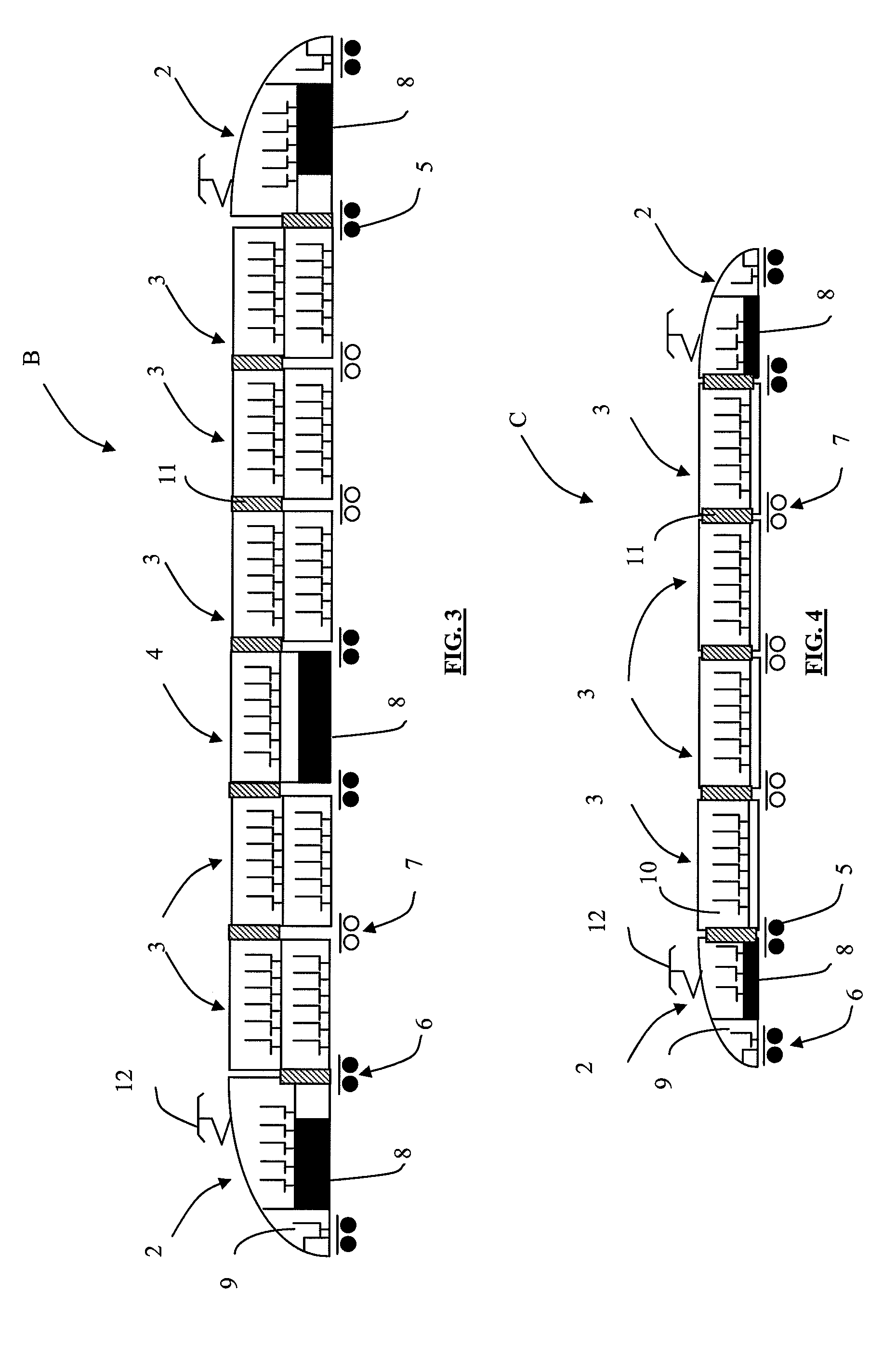
[0068]As illustrated in FIG. 1, the railcar A comprises only single deck carriages. In a variant, the driving carriages 2 and the intermediate carriages 3, 4 are double deck, as illustrated in FIG. 3.

[0069]Advantageously, in a railcar B which has double deck carriages, the lower level of a driving carriage 2 and the motorised intermediate carriage 4 which receives a traction drive 8 is used to accommodate the traction drive(s) 8, the other level being reserved for passengers.

[0070]The passages 11 are placed at the upper level in order to move from one trailer 3 to another. In contrast, the passages between the driving carriages 2 and the adjacent trailers 3 are formed at the lower level. A stairway (not illustrated) which is arranged in the driving carriage 2 and in the trailers 3 allows the upper level to be reached from the access doors (not illustrated) of the carriages 2, 3, 4.

third embodiment

[0071]For a short railcar, in the order of from 120 to 160 m, it is advantageous to reduce the number of motor bogies by removing the motorised intermediate carriage 4 which receives the traction drive(s) 8 and removing the associated motor bogies 6.

[0072]In this manner, in the variant illustrated in FIG. 4, in which the references to the elements which are similar to those of FIG. 1 have been retained, a railcar C is distinguished from that of the preceding embodiments in that it comprises only trailers 3 which have no traction drives 8. The railcar C therefore has no motorised intermediate carriage 4 which receives a traction drive 8.

[0073]The railcar C comprises four motorised bogies 6 which are arranged below the free ends of the driving carriages 2, and in a straddling manner below the end of a driving carriage 2 and the end of the adjacent trailer 3. In accordance with the desired power / mass ratio, from four to eight axles could be motorised, each motor bogie 6 having at least...


PUM


Abstract

This railcar is of the type comprising:carriages including two driving carriages and intermediate carriages;carrier bogies, motor bogies comprising at least one motor axle;traction drives which are capable of supplying electrical energy to the motors of the motor bogies.According to one feature of the invention, all the carriages have passenger compartments, the railcar is completely articulated, the traction drives are arranged in three carriages and a motor bogie is arranged below at least one end of each carriage which receives a traction drive.

Description

TECHNICAL FIELD [0001]The present invention relates to a railcar for passenger transport and more specifically a railcar which can be adjusted in terms of passenger capacity and in terms of maximum speed.BACKGROUND TO THE INVENTION [0002]The architectures of trains or railcars are differentiated depending on whether they have concentrated or distributed motorisation, depending on whether the carriages composing them are connected in an articulated or non-articulated manner, depending on the arrangement and the number of motor and carrier bogies, and depending on whether they are single or double deck.[0003]For reasons of clarity, these various notions are defined in the following paragraphs.[0004]Train or Railcar[0005]A railcar comprises at least one motorised carriage, that is to say, comprising at least one passenger compartment and at least one traction drive. A railcar may thus comprise only motorised carriages or comprise non-motorised carriages and at least one motorised carri...

Claims


Application Information

Patent Timeline
Patent Type & Authority Applications(United States)
IPC IPC(8): B61F3/12
CPCB61D3/10B61C3/00B61D17/20B61D17/14B61D17/22B61D17/00
Inventor PALAIS, GEORGESLHOMMET, MAX
Owner ALSTOM TRANSPORT SA
Learn More