Solution Casting Method

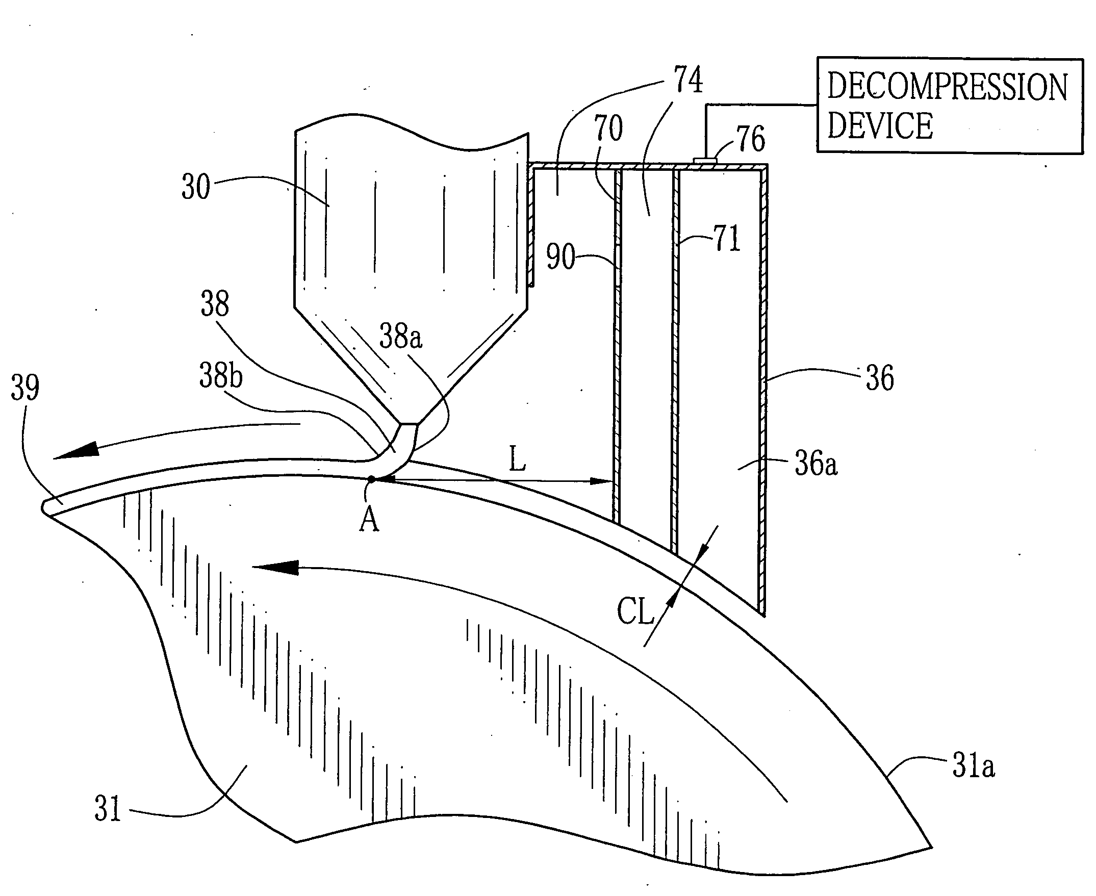
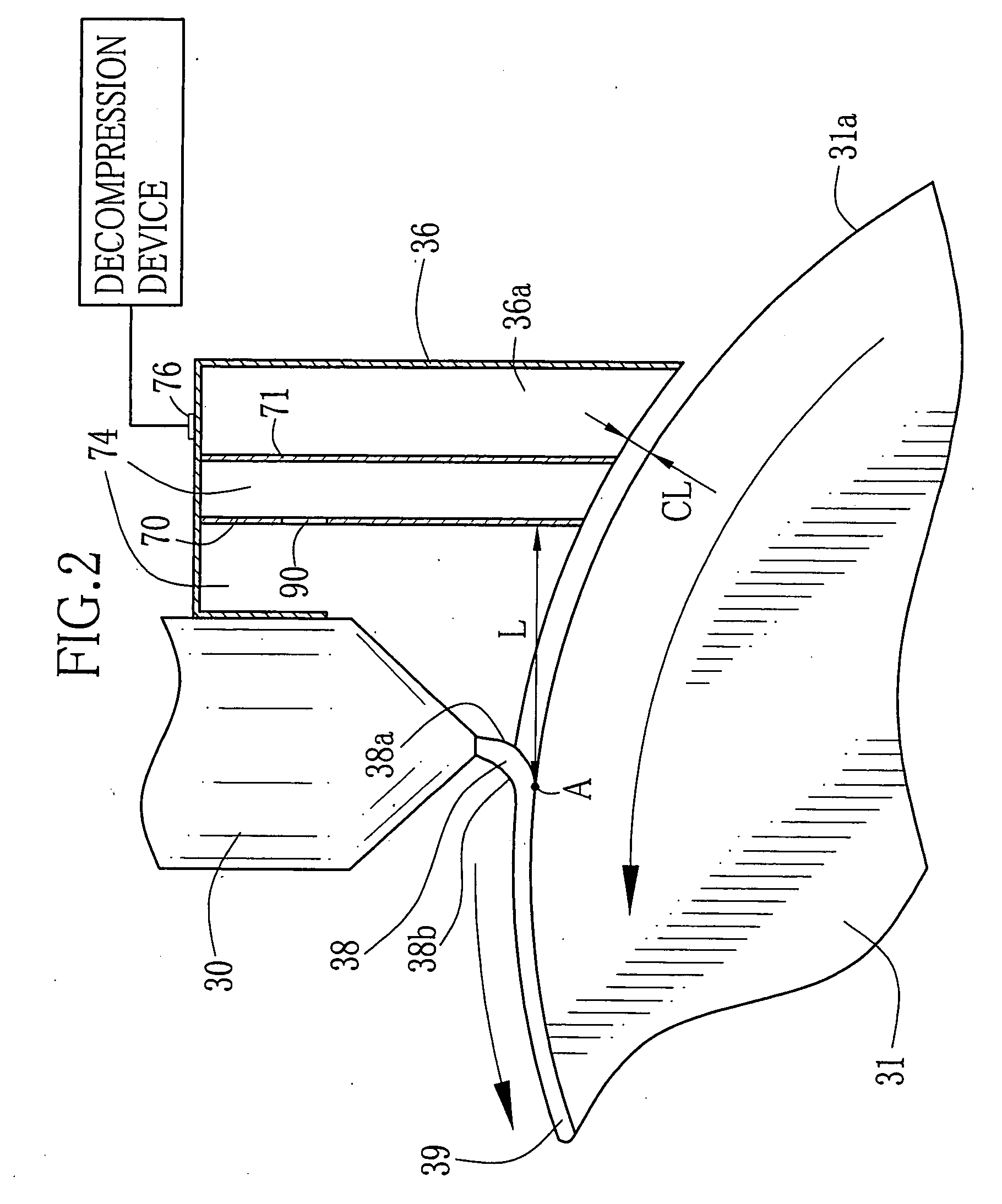
a casting method and film technology, applied in the field of film production methods, can solve problems such as uneven film thickness, and achieve the effects of preventing the change of casting bead thickness, preventing uneven film thickness, and preventing blowing

Inactive Publication Date: 2008-08-14
FUJIFILM CORP
View PDF4 Cites 2 Cited by
  • Summary
  • Abstract
  • Description
  • Claims
  • Application Information

AI Technical Summary

Benefits of technology

[0012]According to the solution casting method of the present invention, the dope including the polymer and the solvent is cast from the casting die to the moving support to form the casting film, and the casting film is peeled from the support and dried to form the film. In this solution casting method, the upstream area from the casting bead is decompressed by the decompression chamber having the plate member extending in the width direction of the support. Accordingly, the air flow is prevented from blowing onto the casting bead so that the changes in the thickness of the casting bead are prevented. Since the casting bead forms the casting film on the support, the unevenness in the film thickness is prevented.
[0013]According to the solution casting film of the present invention, when the distance between the contact position in which the casting bead comes in contact with the support and the plate member is defined as L (mm), L (mm) satisfies 20 mm≦L (mm)≦100 mm. Further, since the opening for discharging the air flow away from the casting bead is formed in the plate member, the casting bead is prevented from being exposed to the air flow. Further, the air flow in the decompression chamber is controlled through the opening of the plate member. Thereby, the air flow from the upstream side from the casting bead is extremely weakened and is prevented from blowing onto the casting bead. Note that when the plural openings are formed in the upper half portion of the plate member in the vertical direction, the air flow control is more facilitated.
[0014]The air flow from the upstream from the casting bead in the support moving direction is effectively prevented by providing plural number of the plate members, for instance, in a range of two to eleven in the upstream with respect to the support moving direction.
[0015]The present invention is more effective in producing a thin film (thickness of approximately 40 μm) than a thick film (thickness of approximately 80 μm). Further, the formation of the casting bead is more stabilized by preventing the air flow from blowing onto the casting bead, and thus the troubles in the production are drastically decreased. Further, when the cellulose acylate is used as the polymer, a thin film with an excellent optical isotropy is produced which is preferably used as the optical function film.

Problems solved by technology

Further, the inventors found out that the air flow enters between the support and the casting bead to cause the unevenness in the film thickness.

Method used


Image

  • Solution Casting Method
  • Solution Casting Method
  • Solution Casting Method

Examples


embodiment 1

[0087]The embodiment 1 is described in the following. However, the present invention is not limited to the embodiment 1. Note that the detailed explanations are given in the experiment 1. Regarding the experiments 2 to 17 according to the present invention and the comparison experiment 18, experiment conditions and the results will be shown together in Table 1.

[0088]Each pts. mass of raw materials used in the embodiment 1 is as follows.

[0089][Composition]

Cellulose triacetate (fine particles whose degree of100pts. masssubstitution is 2.84, viscometric average degree ofpolymerization is 306, moisture content is2.0 mass %, viscosity of 6 mass % of dichloromethanesolution is 315 mPa · s, average particle diameteris 1.5 mm and average variation of the particlediameter is 0.5 mm)Dichloromethane (first solvent)384pts. massMethanol (second solvent)94pts. mass1-Butanol (third solvent)2pts. massPlasticizer A (Triphenylphosphate)7.6pts. massPlasticizer B (diphenylphosphate)3.8pts. massUV agent...

embodiment 2

[0122]The embodiment 2 is described in the following. However, the present invention is not limited to the embodiment 2. Note that the description is carried out in detail in the experiment 19. However, the description of the same experiment conditions as the experiment 1 is omitted. Further, regarding the experiments 20 to 27 according to the present invention and the comparison experiment 28, the experiment conditions and the results will be shown together in the Table 2 later.

[0123]Each pts. mass of the raw materials used in the experiment 19 is shown below.

[0124][Composition]

Cellulose triacetate (degree of substitution is 2.83,28pts. massviscometric average degree of polymerization is 320,moisture content is 0.4 mass %, viscosity of 6 mass %of dichloromethane solution is 305 mPa · s)Methyl Acetate75pts. massCyclopentanone10pts. massAcetone5pts. massMethanol5pts. massEthanol5pts. massPlasticizer A (Dipentaerythritol hexaacetate)1pts. massPlasticizer B (Triphenylphosphate)1pts. ma...


PUM

PropertyMeasurementUnit
distanceaaaaaaaaaa
moving speedaaaaaaaaaa
thicknessaaaaaaaaaa

Abstract

A dope including a polymer and a solvent is discharged from a casting die (30) to a casting drum (31) while forming a casting bead (38). An upstream side (38a) area of the casting bead (38) is decompressed by a decompression chamber (36) to (atmospheric pressure—300)Pa. Air shielding plates (70, 71) are provided inside the decompression chamber (36). Openings (90) are respectively formed in upper half portions of the air shielding plates (70, 71). A distance L (mm) between a contact position A of the casting bead (38) and the air shielding plate (70) is set in the range of 20 mm to 100 mm. After the casting bead (38) forms a casting film (39) on the casting drum (31), the casting film (39) is peeled and dried to obtain a TAC film.

Description

TECHNICAL FIELD [0001]The present invention relates to a method for producing a film, more particularly, the present invention relates to the method for producing the film used as a protection film for a polarizing filter and an optical compensation film in an LCD device, or a photographic support film.BACKGROUND ART [0002]A cellulose acylate film, particularly a cellulose triacetate (TAC) film produced from a TAC with average acetylation degree from 57.5% to 62.5% is used as a photographic support film for a photographic photosensitive material owing to its toughness and fire-resistant property. Further, because of its excellent optical isotropy, the TAC film is used as a protection film for a polarizing filter, an optical compensation film, for instance, a wide view film and the like in an LCD device whose market is expanding recently.[0003]Usually, the TAC film is produced by a solution casting method. The solution casting method, compared to other film producing method such as a...

Claims


Application Information

Patent Timeline
Patent Type & Authority Applications(United States)
IPC IPC(8): B29C41/26
CPCB29C41/26B29K2001/00B29C47/8865B29C47/0021B29C48/08B29C48/916B29C41/24B29C41/50B29L2007/00
Inventor HIGUCHI, JIROKATO, MORITOSUZUKI, YUJI
Owner FUJIFILM CORP
Why Eureka
Try Eureka