Screw Joint for Oil Well Tubing

a technology for oil well tubing and screw joints, which is applied in the direction of screw threaded joints, hose connections, mechanical equipment, etc., can solve the problems of solving several problems of conventional special screws, and achieve excellent sealing performance and maintainability

Inactive Publication Date: 2008-08-14
METAL ONE CORP
View PDF14 Cites 15 Cited by
  • Summary
  • Abstract
  • Description
  • Claims
  • Application Information

AI Technical Summary

Benefits of technology

[0024]With a screw joint for oil well tubing according to the present invention, it is possible to provide an economic oil well tubing system, excellent in seal performance and maintainability.
[0025]FIG. 1 is a schematic view showing a basic configuration of a screw joint of an example.
[0026]FIG. 2 is a graph showing a calculation result of a contact surface pressure Pc after fitting, in a combinat

Problems solved by technology

That is to say, the conventional special

Method used


Image

  • Screw Joint for Oil Well Tubing
  • Screw Joint for Oil Well Tubing
  • Screw Joint for Oil Well Tubing

Examples


embodiment 1

[0031]An embodiment 1 of the present invention will be successively described in detail in accordance with ways of solving the above-described problems to be solved.

[0032]First, relating to the first problem;

[0033]as described above, conventionally, an upper limit of a maximum contact surface pressure Pcmax of a seal portion has been designed to satisfy a formula

Pcmax>(yield stress or of screw joint material),

from the viewpoint of preventing a plastic deformation of the seal portion when fitting.

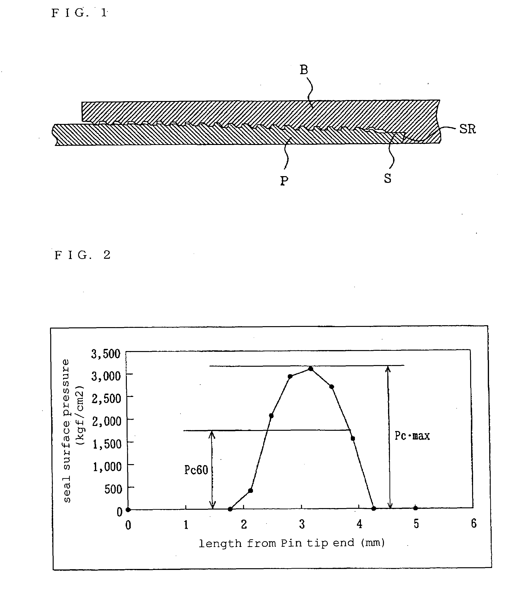
[0034]However, in practice, the seal portion plastically deforms when fitting a screw portion, even when the maximum contact surface pressure Pcmax of the seal portion is lower than the yield stress, so that there is a case in which a predetermined contact surface pressure Pc is not obtained by the plastic deformation, when the screw portion is wound back and fitted again.

[0035]In order to prevent this, in the Embodiment 1 of the present invention, the upper limit of the maximum contact surf...

example 1

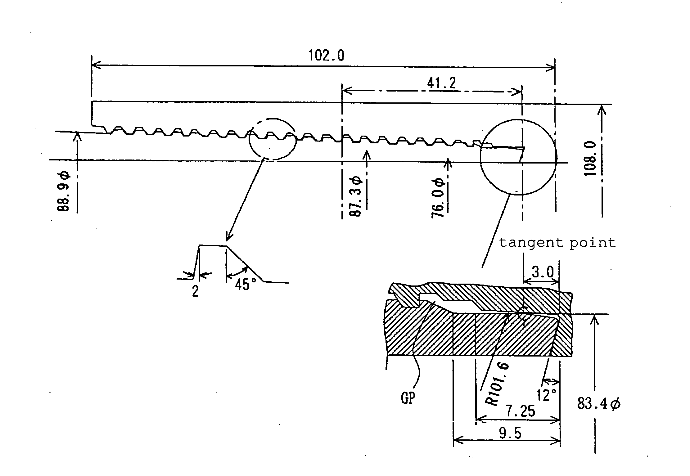
[0048]Based on the above-described embodiment, an example of the screw joint for oil well tubing for API grade N80 tubing, in which outer diameter×tube wall thickness=3·½″ (88.9 mm)×0.254″ (6.45 mm), will be described.

[0049]FIG. 1 is a schematic view showing a basic configuration of the screw joint of Example 1.

[0050]FIG. 3 is a schematic view showing a basic configuration of the seal portion of the Example 1.

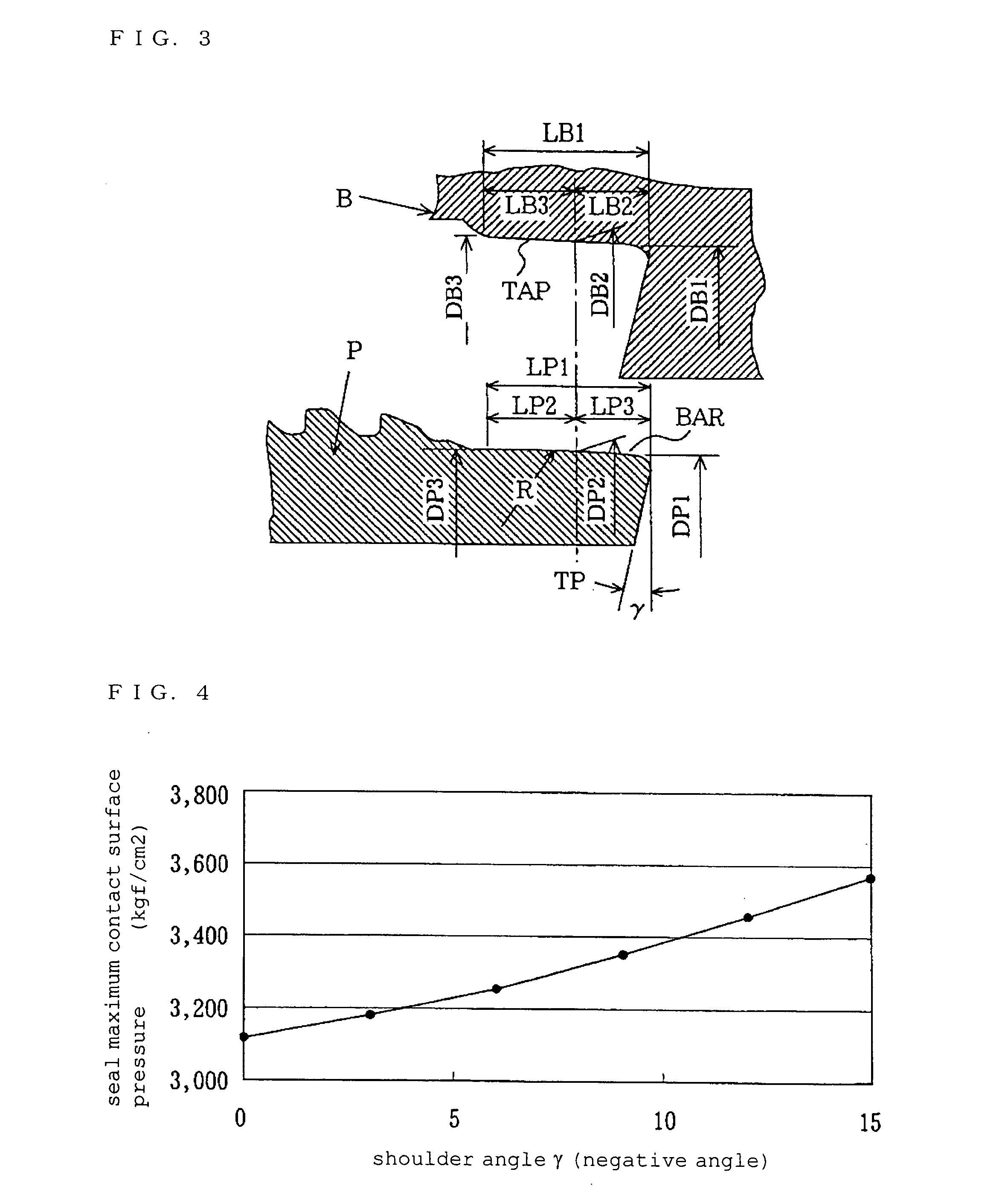
[0051]FIG. 4 is a graph showing an effect of the shoulder angle to the surface pressure.

[0052]FIG. 5 is a schematic view showing a cross-sectional shape of the screw of the tapered screw portion of the Example 1.

[0053]In the drawings, reference numeral P represents the Pin having the seal portion with the convex curved surface shape, reference numeral B represent the Box having the tapered seal portion, reference numeral S represents the seal portion, reference numeral SR represents the shoulder portion, reference numeral TAP represents the tapered seal portion, reference numer...


PUM


Abstract

There is provided a screw joint for oil well tubing, excellent in seal performance and having a high maintainability.
A screw joint for oil well tubing comprising a male screw tube equipped with a seal forming portion having a convex curved surface shape on a tip end portion of the tube and a female screw tube equipped with a tapered seal portion, wherein when the convex curved surface shape comes into contact with the tapered seal portion, a contact surface pressure Pc60 equivalent to 60% of a maximum contact surface pressure Pcmax applied to a contact surface is larger than an inner pressure Pi applied to the screw joint and is smaller than a proportional limit or of a screw joint material, wherein a taper angle θs of the tapered seal portion and an angle θt of a tapered screw satisfy a formula θs≧θt, and curvature radius R of the convex curved surface shape is not smaller than 90 mm and not larger than 170 mm, wherein the angle θs is from 1.4 degree to 9.5 degree at an apex angle, wherein a length of the convex curved surface shape in an axial direction is at least not smaller than 1.5 mm backward and forward from a tangent point, and wherein a surface roughness H of the convex curved surface and the tapered seal portion is not larger than 12s.

Description

TECHNICAL FIELD[0001]The present invention relates to a screw joint for oil well tubing.BACKGROUND ART[0002]Recently, oil fields and gas fields to be excavated become deeper and more highly pressurized.[0003]Following the circumstance, it is required that a screw joint used for oil well tubing has a high performance in a sealing performance and durability. In order to cope with this, a number of special screws have been developed.[0004]The conventional special screw is configured to form a metal seal by a tip end of a Pin (male screw) and an inside of a Box (female screw), as shown in FIG. 1. Many researches and developments are made for a seal shape of the special screw.[0005]As one of them, a seal referred to as a tangent point seal, formed by a combination of the Pin having a seal surface with a convex curved surface shape and the Box having a tapered seal surface, has been developed as the screw relatively reliable as disclosed in Japanese Patent Application Laid-Open No. 61-648...

Claims


Application Information

Patent Timeline
IPC IPC(8): F16L15/04F16L25/00E21B17/042F16L15/06
CPCF16L15/004E21B17/042
Inventor SUZUKI, TERUAKI
Owner METAL ONE CORP
Why Eureka
Try Eureka