
Threat Detection System

a detection system and target technology, applied in direction finders using radio waves, instruments, reradiation, etc., can solve the problems of unreliable, simple and affordable weapons, unreliable panoramic radar, and failure to provide sufficient precision or warning time for reliably operating countermeasures, so as to reduce the efficacy of offensive projectiles.

Active Publication Date: 2008-08-14
STATE OF ISRAEL MINIST OF AGRI & RURAL DEV AGRI RES ORG (A R O) (VOLCANI CENT)
View PDF36 Cites 39 Cited by
  • Summary
  • Abstract
  • Description
  • Claims
  • Application Information

AI Technical Summary

Benefits of technology

The present invention is a detection system for detecting the launch of offensive projectiles, particularly rockets or missiles, from a short range towards a platform. The system uses an optical detection system with an image detector array to capture images of the launch and process them to identify a flash event. The system has a high sensitivity and can detect the direction of the flash event. The system can be used in conjunction with a radar detection system to provide a more comprehensive detection of approaching offensive projectiles. The system can also include an active protection system to neutralize or reduce the efficacy of the offensive projectile. The technical effects of the invention include improved detection and protection of platforms from offensive projectiles.

Problems solved by technology

Designed specifically for close combat operations, this reliable, simple and affordable weapon poses a serious threat to even the heaviest tanks when used by determined fighters, in both urban and guerrilla warfare.
It has been found, however, that for short range applications of less than 100 meters, panoramic radar becomes unreliable, failing to provide sufficient precision or warning time for reliably operating countermeasures.
Bolometric imaging sensors, however, provide relatively low sensor resolution, requiring multiple sensors to cover a panoramic field of view.
This fact, combined with the high unit cost of such sensors, renders such detection systems economically unviable for large scale installation on a wide range of platforms.

Method used


Image

  • Threat Detection System
  • Threat Detection System
  • Threat Detection System

Examples


Embodiment Construction

[0029]The present invention is a detection system for detecting rockets or missiles launched from short range towards a platform.

[0030]The principles and operation of detection systems according to the present invention may be better understood with reference to the drawings and the accompanying description.

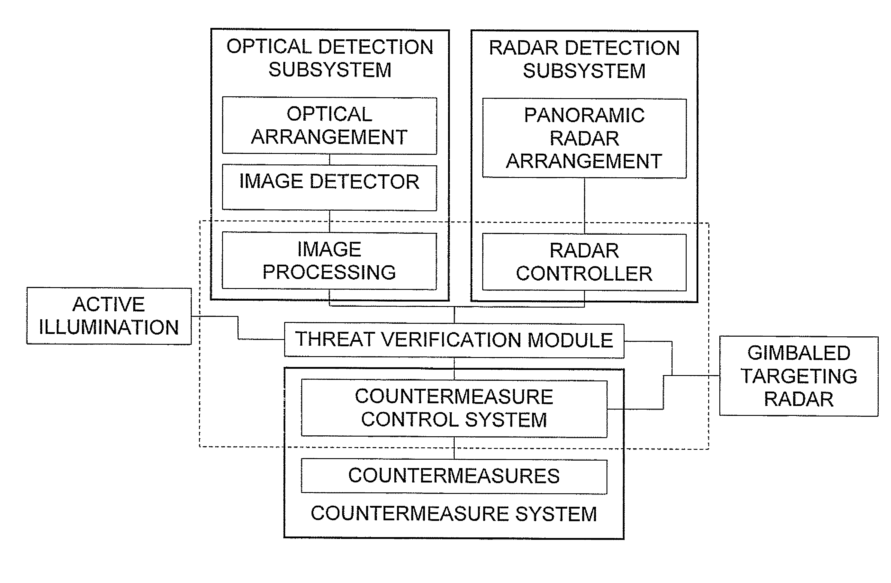
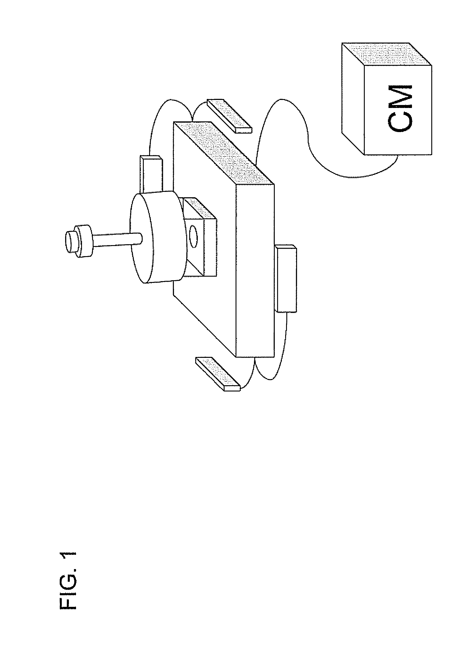
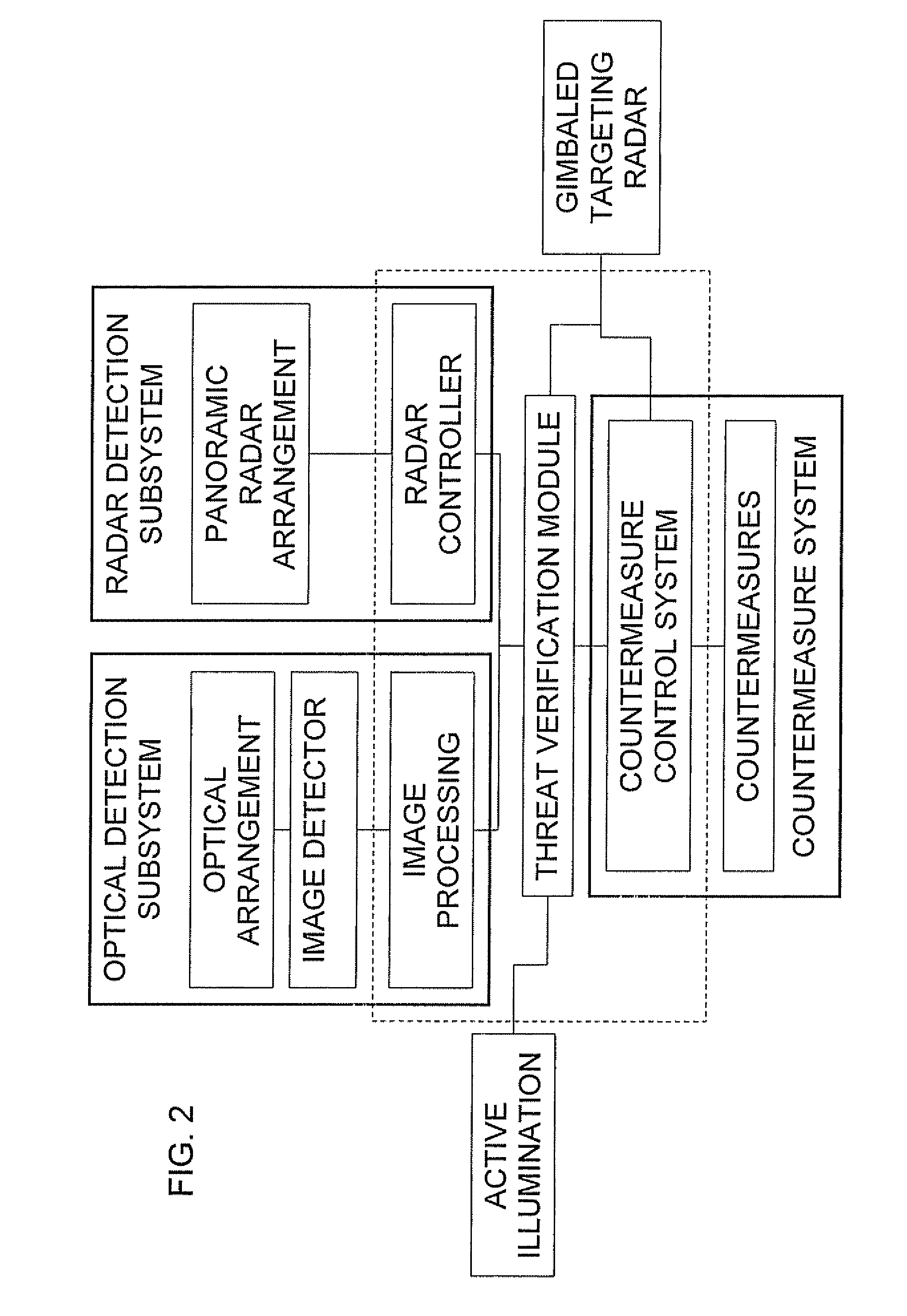
[0031]Referring now to the drawings, FIGS. 1 and 2 show generally an active protection system, generally designated 10, constructed and operative according to the teachings of the present invention, for protecting a platform from offensive projectiles. By way of introduction, referring to FIG. 2, the present invention relates primarily to an optical detection system 12 for detecting launch of offensive projectile which is believed to be patentable in its own right, but which may be used to advantage as a subsystem of active protection system 10. It should be noted that optical detection system 12 may be used as a free standing system, for example, for operating an audio alarm to ...


PUM


Abstract

An optical detection system for detecting launch of an offensive projectile. The detection system includes an image detector array, an optical arrangement for focusing on to the image detector array, and a processing system associated with the image detector array. The processing system is configured to derive a series of frames from the image detector, to process the series of frames to identify a flash event and to generate and output that indicates a direction of the flash event.

Description

FIELD AND BACKGROUND OF THE INVENTION[0001]The present invention relates to threat detection systems and, in particular, it concerns a detection system for detecting rockets or missiles launched from short range towards a platform.[0002]In the continuing conflict in Iraq, shoulder fired rocket propelled grenades (RPGs) were once again proven a potent weapon. RPGs have performed impressively in all post WWII conflicts, especially in Vietnam, Afghanistan and Chechnya. Designed specifically for close combat operations, this reliable, simple and affordable weapon poses a serious threat to even the heaviest tanks when used by determined fighters, in both urban and guerrilla warfare. Inexperienced RPG operators can engage a stationary target effectively from 150-300 meters, while experienced users could kill a target at up to 500 meters, and moving targets at 300 meters. In post war Iraq, RPGs have caused the death of over fifty percent of U.S. soldiers killed in action.[0003]One approach...

Claims


Application Information

Patent Timeline
Patent Type & Authority Applications(United States)
IPC IPC(8): G01S13/00F42B15/00G01S3/02
CPCF41H7/00F41H11/02G01S3/784G01S13/867G08B13/18H04N7/18G01S13/66
Inventor BENAYAHU, YAIRVOSKOBOINIK, ASHER
Owner STATE OF ISRAEL MINIST OF AGRI & RURAL DEV AGRI RES ORG (A R O) (VOLCANI CENT)
Learn More