

Optical sheet and display device including the same
a display device and optical sheet technology, applied in the field of optical sheets, can solve the problems of reducing the vertical viewing angle deteriorating the optical efficiency reducing the brightness of the display device, so as to achieve the effect of improving brightness and brightness
- Summary
- Abstract
- Description
- Claims
- Application Information
AI Technical Summary
Benefits of technology
Problems solved by technology
Method used
Image

Examples
examples 1-5
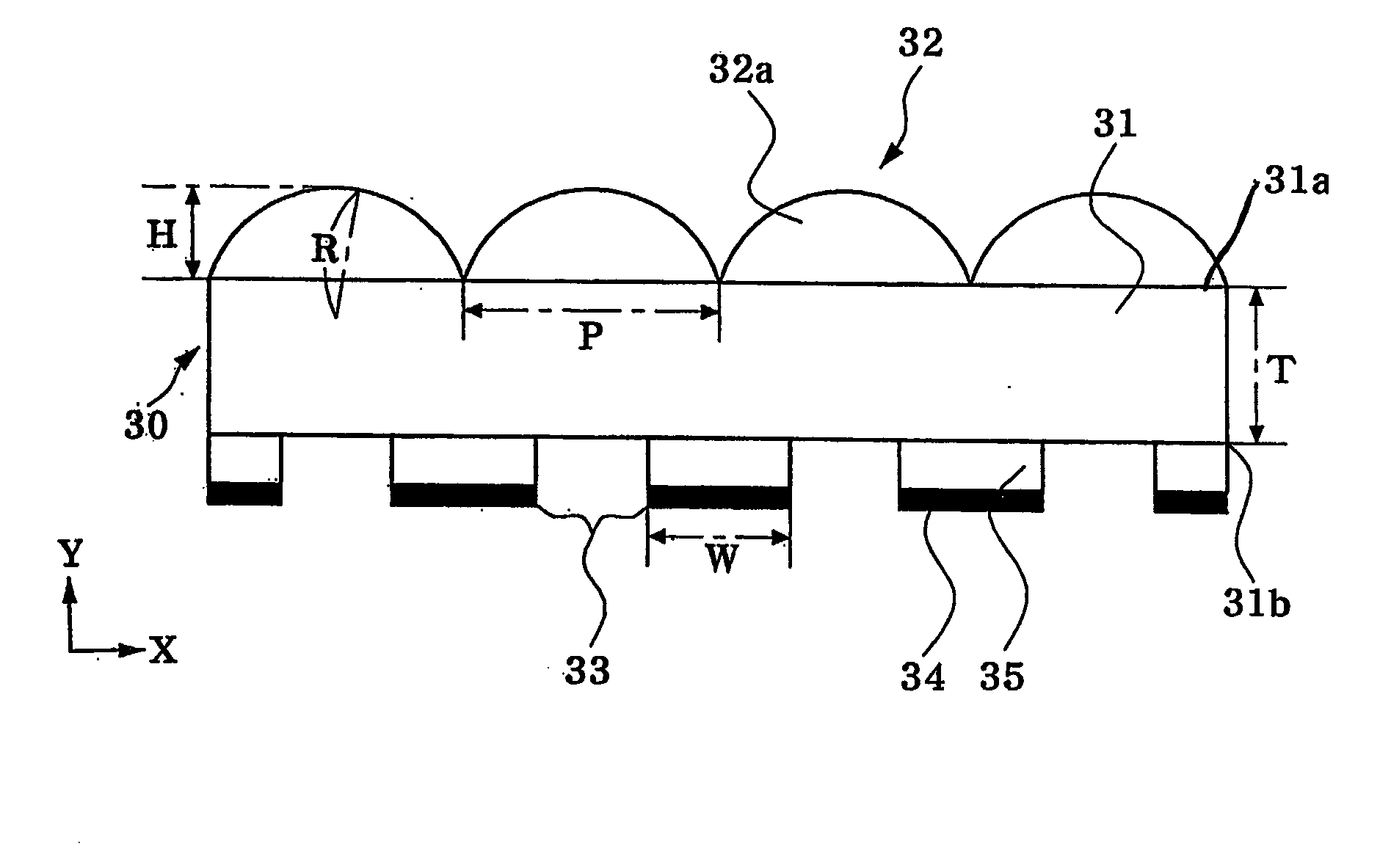
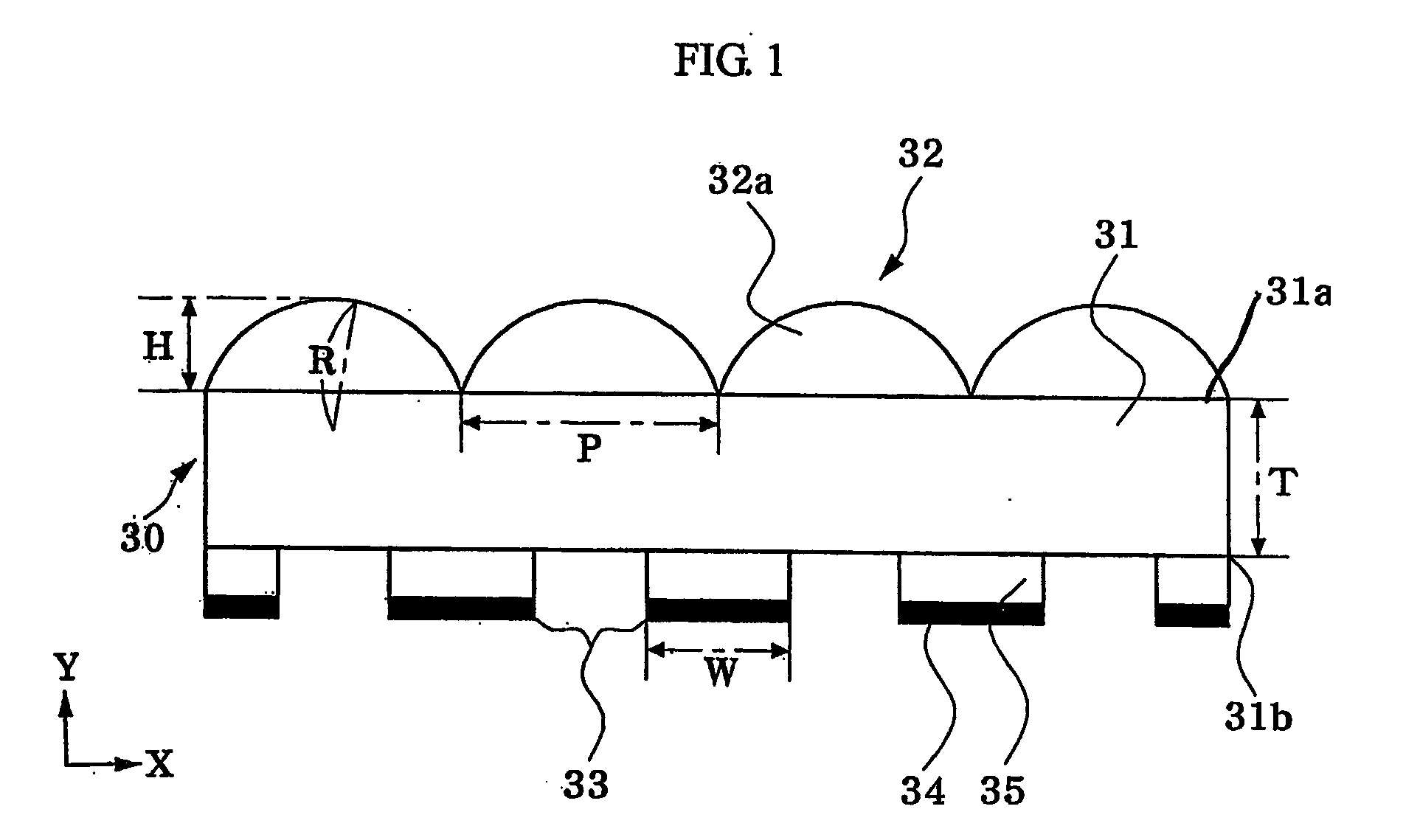
[0057]Optical sheets were formed according to embodiments of the present invention. The optical sheets were formed of polycarbonate having a refractive index of 1.59. The optical sheets had micro-lenses with a radius of curvature of 100 μm and HR ratio of 1, openings having width and length of 100 μm and 106 μm, respectively, and protrusion having a height of 30 μm. The front focal length of the micro-lenses 32a in the optical sheet was calculated according to Equation 9 below to be 170 μm, where r1 refers to a radius of curvature of a lens surface closest to the light source and r2 refers to a radius of curvature of a lens surface furthest from the light source.
1f=(n-1)(1r1-1r2)Equation9
[0058]The thickness T of the substrate of each optical sheet was varied between 60 μm and 180 μm, and brightness and viewing angle with respect to each optical sheet was calculated. Calculations were performed via a numerical analysis.
[0059]The brightness was calculated by setting a total luminous f...
examples 6-10
[0061]Optical sheets were formed according to embodiments of the present invention. The optical sheets were formed of polycarbonate having a refractive index of 1.59. The optical sheets had micro-lenses with a radius of curvature of 100 μm and HR ratio of 0.8, a substrate having a thickness of 100 μm, and protrusion having a height of 10 μm. The front focal length of the micro-lenses was 170 μm. The width of the intercepting reflector layer of each optical sheet was varied between 0 μm and 80 μm, and brightness and viewing angle with respect to each optical sheet were calculated. Calculations were performed via a numerical analysis. Results are reported in Table 2 and in FIGS. 11A-11E.
TABLE 2ExampleExample 6Example 7Example 8Example 910Width of020406080InterceptingReflectorLayer (μm)Center56395521581763277371Brightness(nit)Viewing96 * 9684 * 8476 * 7670 * 7060 * 60Angle (°)
[0062]As can be seen in Table 2 above, an increase in width of the intercepting reflector layer increased the c...
examples 11-30
[0063]Optical sheets were formed according to embodiments of the present invention. The optical sheets were formed of polycarbonate having a refractive index of 1.59. The optical sheets had a substrate having a thickness of 100 μm, protrusion having a height of 10 μm, and a viewing angle of 80°. The radius of the micro-lenses and width of the intercepting reflector layer of each optical sheet were varied, and brightness and rate of intercepting reflector layer were calculated. The rate of the intercepting reflector layer is defined as a fraction of a size of the intercepting reflector layer relative to the lens, i.e., a ratio between the width of intercepting reflector layer and the lens pitch multiplied by 100. Results are reported in Table 3.
TABLE 3Radius ofCenterWidth ofRate ofCurvatureBright-InterceptingLensInterceptingof Micro-HRnessReflectorPitchReflectorLens (R)Ratio(nit)Layer (μm)(μm)Layer (%)Ex. 11100 μm0.654633718320.2Ex. 120.756333419117.8Ex. 130.855792919614.8Ex. 140.957...
PUM
 Abstract
Description
Claims
Application Information