Microphone with dual transducers

a technology of electroacoustic transducers and microphones, applied in the field of microphones, can solve the problems of high undamped peak frequency, signal-to-noise ratio, and microphone overload in the presence of ultrasonic signals

Inactive Publication Date: 2008-08-14
SONION NEDERLAND
View PDF3 Cites 70 Cited by
  • Summary
  • Abstract
  • Description
  • Claims
  • Application Information

AI Technical Summary

Problems solved by technology

With both MEMS microphones and traditional electret condenser microphones, the challenge is to improve the signal-to-noise ratio.
Unfortunately, low acoustical resistance results in very high undamped peak frequencies.
Peak frequencies higher than 15 kHz, however, can result in overload of the microphone in the presence of an ultrasonic signal.

Method used


Image

  • Microphone with dual transducers
  • Microphone with dual transducers
  • Microphone with dual transducers

Examples


Embodiment Construction

[0022]Following is a detailed description of various embodiments of the invention with reference to the drawings. It should be noted that the drawings are provided for illustrative purposes only and are not intended to be manufacturing drawings or blueprints, nor are they drawn to any particular scale.

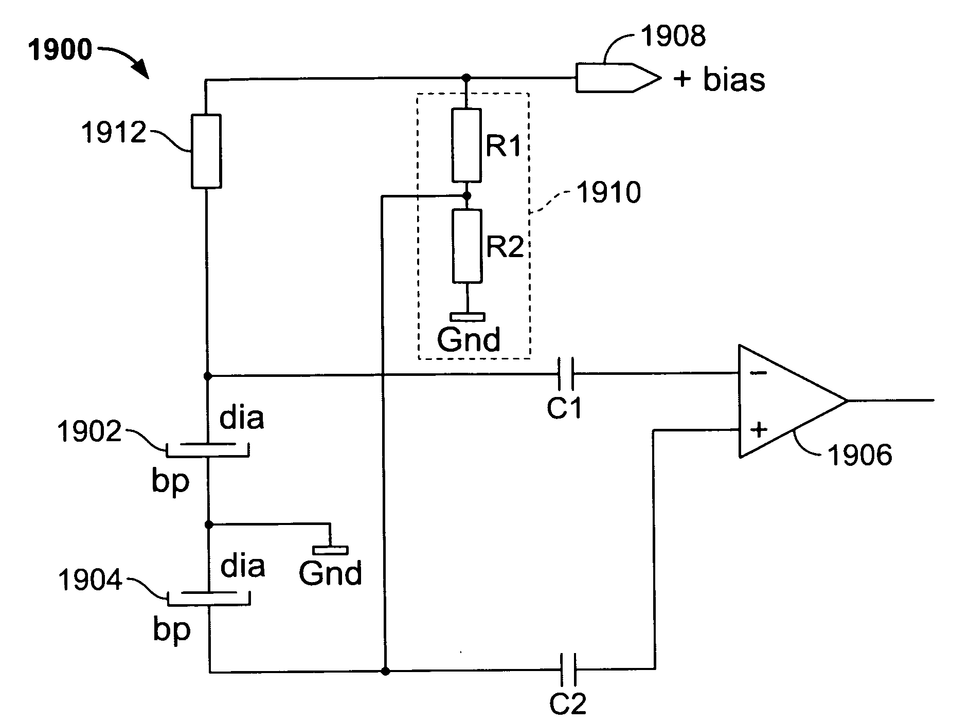
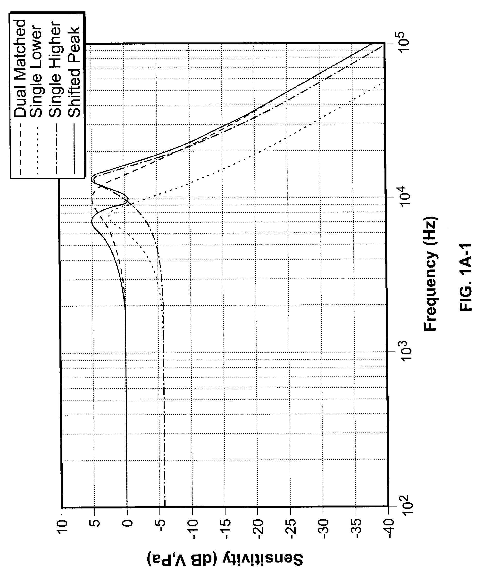
[0023]As mentioned previously, the peak frequency of a microphone should be between 9 and 15 kHz for optimum performance in applications such as hearing aids. In accordance with embodiments of the invention, a desirable peak frequency may be achieved by providing a single microphone with two electroacoustic transducers, each transducer having a peak frequency that is separated from the other peak frequency by a predetermined minimum amount. The deliberate and specific use of unmatched electroacoustic transducers can produce a desirable resultant peak frequency without compromising the amount of noise damping for the microphone. Such an arrangement is in contradistinction to the case wh...


PUM


Abstract

Microphone is disclosed having unmatched electroacoustic transducers. The microphone may be a traditional ECM microphone, or it may be a MEMS microphone. Each of the unmatched electroacoustic transducers may have its own peak frequency selected so that the electroacoustic transducers together produce a desirable resultant peak frequency. The unmatched electroacoustic transducers may have different package sizes, front volumes, back volumes, and / or diaphragm tensions, thicknesses, lengths, widths, and / or diameters. In some embodiments, the microphone may have different backplate charging and / or output signal amplification schemes for the electroacoustic transducers. Where the microphone is a MEMS microphone, voltage generation and output signal amplification are provided by an integrated circuit that may be mounted either within a front volume of one of the electroacoustic transducers or adjacent to one of the electroacoustic transducers.

Description

CROSS REFERENCE TO RELATED APPLICATION[0001]This application claims the benefit of U.S. Provisional Application No. 60 / 889,740, filed Feb. 13, 2007.FIELD OF THE INVENTION[0002]The present invention relates generally to microphones and, more particularly, to a microphone having dual electroacoustic transducers.BACKGROUND OF THE INVENTION[0003]A typical acoustic transducer, such as those used in microphones, includes a flexible diaphragm and a stiff backplate substantially parallel to the flexible diaphragm. The diaphragm divides the acoustic transducer into a front volume and a back volume and forms a capacitor with the backplate. For MEMS (micro electromechanical system) microphones, a voltage generator supplies and maintains a voltage on the backplate. An example of a MEMS microphone may be found, for example, in commonly-assigned U.S. Published Application No. 20040120540, which is incorporated herein by reference. No voltage generator is needed to maintain a voltage on the backpl...

Claims


Application Information

Patent Timeline
Patent Type & Authority Applications(United States)
IPC IPC(8): H04R25/00
CPCH04R1/222H04R19/04H04R19/005H04R1/2807
Inventor HALTEREN, AART ZEGER VAN
Owner SONION NEDERLAND
Why Eureka
Try Eureka