Pon System With a Remote Upstream Repeater

a technology of remote upstream repeater and pon system, which is applied in the field of coupler units, can solve the problems of high cost of the customer's optical network unit (onu), and achieve the effects of cost-effective upstream access speed, high bandwidth, and low loss

Inactive Publication Date: 2008-08-14
NAT ICT AUSTRALIA
View PDF3 Cites 13 Cited by
  • Summary
  • Abstract
  • Description
  • Claims
  • Application Information

AI Technical Summary

Benefits of technology

[0028]Multi-mode fibres or polymer fibres can be used in the distribution part of the PON system making the system highly compatible with the existing fibre infrastructure in a building; for fibre to the home or desktop as well as other optical LAN applications. Upstream access speed can be cost-effectively upgraded as demand grows.
[0029]Upstream transmission for the feeder part of the PON system is possible using a low specification upstream laser / LED transmitter at the coupler unit since there are low losses in the upstream path.
[0030]The invention may be used to replace asymmetric digital subscriber line (ADSL) or very-high speed digital subscriber line (VDSL) based fibre to the curb (FTTC) systems. The current copper solutions are limited in length and data rate (up to 1.5 km at 15 Mb / s, or up to 300 m at 52 Mb / s). The invention can offer higher bandwidth and longer distance at much lower cost and, considering the typical asymmetric access traffic pattern and future upgrade to 1.25 Gb / s, is more efficient than any copper solutions. The invention can be also applied to enterprise networks by replacing a current active hub by a star coupler and repeater for fibre to the desktop (FTTD).

Problems solved by technology

However, large scale PON deployment has to date been frustrated by the high-cost of the customer's optical network unit (ONU) which is required at each customer's premises and contains a costly laser transmitter.

Method used


Image

  • Pon System With a Remote Upstream Repeater
  • Pon System With a Remote Upstream Repeater
  • Pon System With a Remote Upstream Repeater

Examples


Embodiment Construction

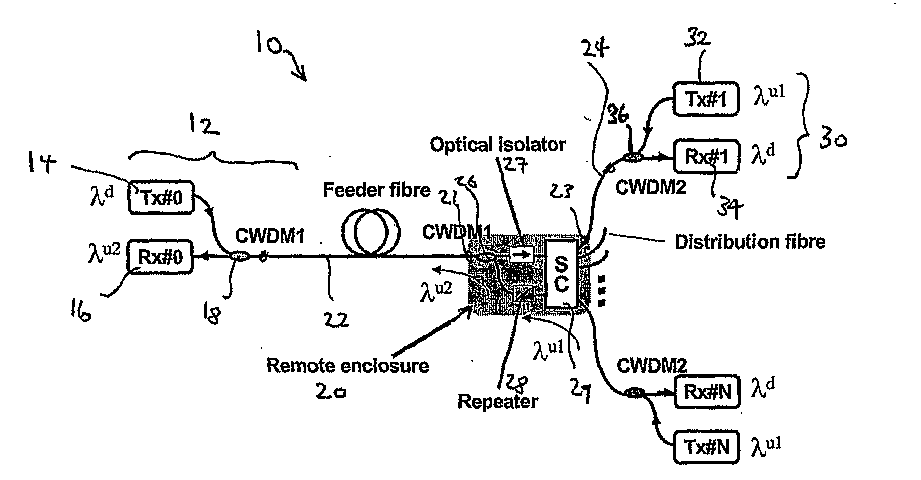
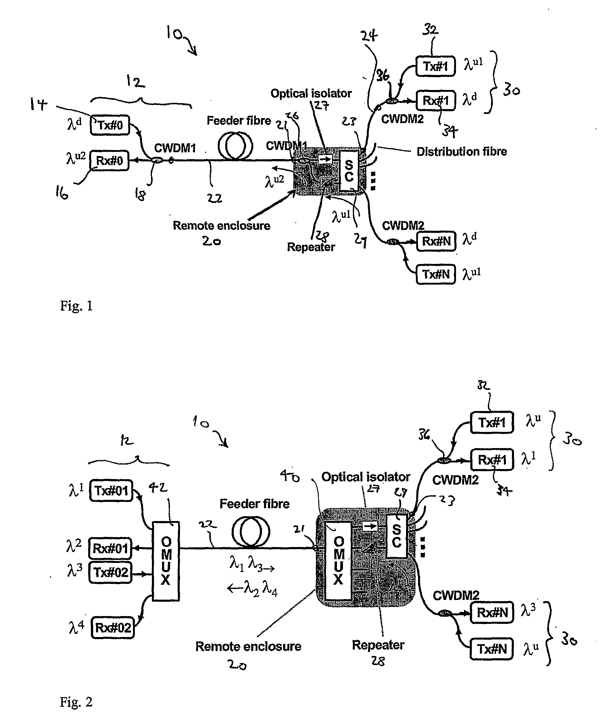
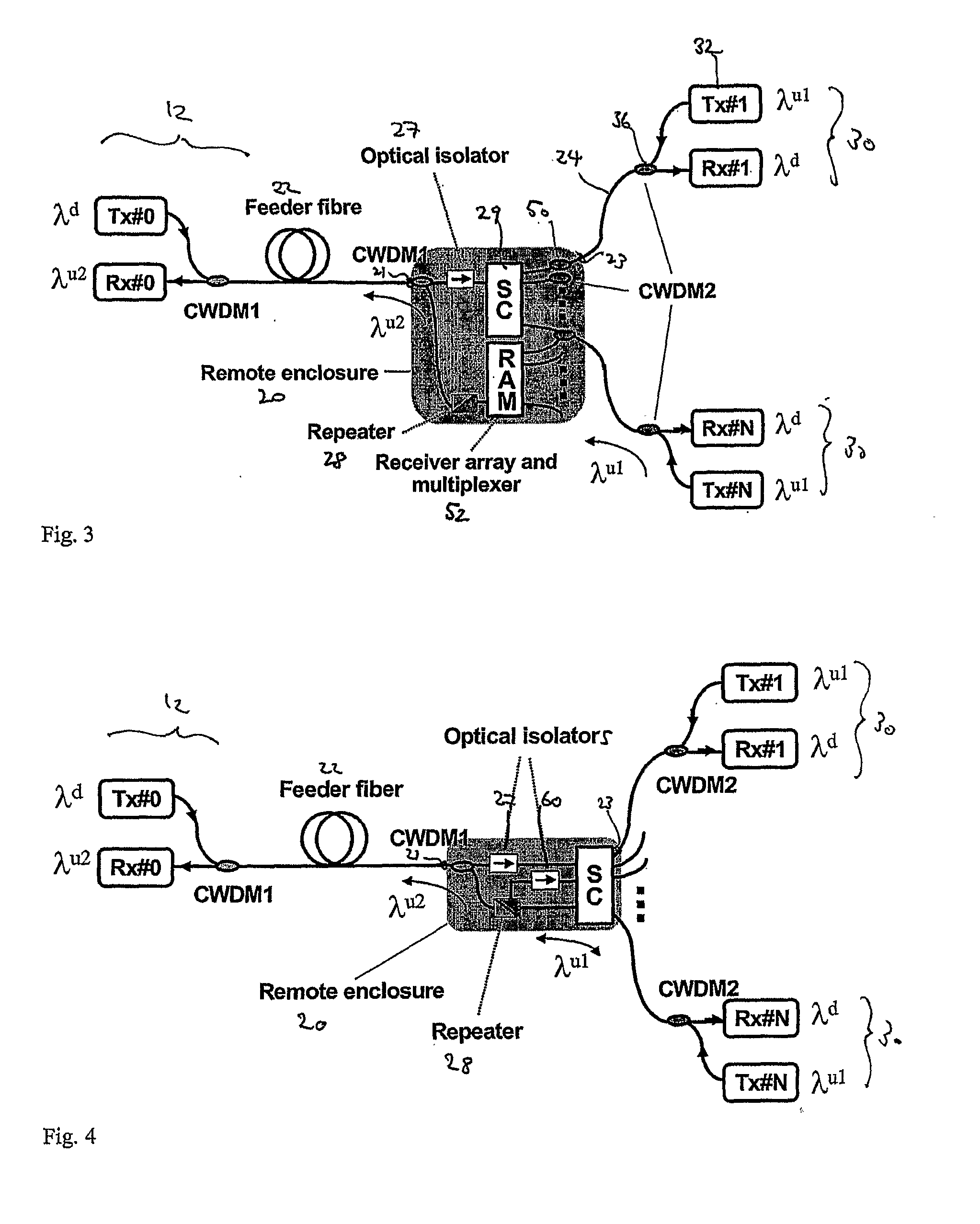
[0036]Referring first to FIG. 1, a passive optical network (PON) 10 consists of an optical line terminal 12 having a single downstream transmitter 14, a single upstream receiver 16 and a coarse wavelength division multiplexer 18.

[0037]A coupler unit 20 is located remote from the line terminal 12, and a feeder side port 21 is connected to terminal 12 by a single feeder fibre 22. A number (N) of optical network units 30 are clustered around the coupler unit 20, and a distribution side port 23 is connected to each network unit 30 by respective distribution fibres 24. The distribution side fibres 24 are typically no more than a few kilometres in length. The coupler unit enclosure 20 contains a coarse wavelength division multiplexer 26, an optical isolator 27, an optical repeater 28, a single 2×N optical star coupler 29, and a power regulation circuit (not shown) for the repeater. Because of the need for power, the enclosure will generally be installed near or inside a customer building ...


PUM


Abstract

A signal coupler (20) for a passive optical network (PON) system is disclosed. The coupler (20) includes a first port for two-way feeder side communication with a PON terminal (12), a star coupler (29), other ports (23) for two-way distribution side communication with each of plural remote optical network units (ONUs) (30), and a repeater (28) installed on the upstream signal path from the ONUs (30) to the PON terminal (12). Upstream signals from ONUs (30) are received by the repeater (28) without passing through the star coupler (29) by using a coarse wavelength division multiplexer (50) on each distribution fibre and taking out the upstream light before arrival at the star coupler (29) and redirecting it to a receiver array and multiplexer (52). The repeater (28) regenerates each upstream signal and changes its wavelength.

Description

CROSS-REFERENCE TO RELATED APPLICATIONS[0001]The present application claims priority from Australian Provisional Patent Application No 2004905387 filed on 17 Sep. 2004, the content of which is incorporated herein by reference.TECHNICAL FIELD[0002]This invention concerns a coupler unit for a passive optical network (PON) system, and in particular a coupler unit to simplify the required functionality of customer optical network units (ONUs) associated with the coupler unit. In a further aspect the invention concerns the PON system containing an OLT, the coupler unit and the ONUs.BACKGROUND ART[0003]PONs first appeared in the late 1980's and promised to provide cost-effective fibre to the home (FTTH). A PON system is typically envisaged with an optical line terminal (OLT) at a central hub, a single feeder fibre extending long distances from the central hub to a coupler unit, and many remote customer optical network units (ONUs) clustered around each coupler unit. Each coupler unit typi...

Claims


Application Information

Patent Timeline
Patent Type & Authority Applications(United States)
IPC IPC(8): H04J14/00H04B10/27H04B10/2581H04B10/272H04B10/29H04B10/299H04B10/524H04B10/572H04B10/58
CPCH04B10/272H04J14/0226H04J14/0227H04J14/028H04J14/0252H04J14/0283H04J14/0246H04J14/0247H04J14/0282H04B10/27H04J14/02G02B6/28G02B6/293
Inventor CHAE, CHANG-JOONTUCKER, RODNEY STUART
Owner NAT ICT AUSTRALIA
Why Eureka
Try Eureka