
Image Data Communication Apparatus

Inactive Publication Date: 2008-08-14
FRONTIERS
View PDF12 Cites 4 Cited by
  • Summary
  • Abstract
  • Description
  • Claims
  • Application Information

AI Technical Summary

Benefits of technology

[0011]Packets to be transmitted are forcibly distributed to a plurality of communication lines with the arrangement order assigned thereto. As a result, high-quality and large-capacity packet transmission becomes possible with small capacity communication lines.
[0020]Packets can be equally distributed to a plurality of communication lines according to a given rule, making it easy for the receiving side to perform rearrangement control.
[0023]This configuration narrows down the behavior of packets to “PASS” and “DISCARD”, making it easy for the gate to perform packet distribution control.
[0038]There is a possibility that a communication failure is currently occurring or will occur in a communication line in which the number of code errors exceeds a threshold value. Therefore, the communication line in which the number of code errors exceeds a threshold value is previously excluded from packet distribution destination lists to thereby prevent a failure of reproduction of original image data.

Problems solved by technology

In such high-image quality television broadcast systems, an extremely large amount data is transmitted and, therefore, it is difficult to perform real-time transmission via an ADSL broadband network.
However, when traffic is increased due to an increase of subscribers, communication speed decreases to lead to degradation of signal quality.

Method used


Image

  • Image Data Communication Apparatus
  • Image Data Communication Apparatus
  • Image Data Communication Apparatus

Examples


example 1

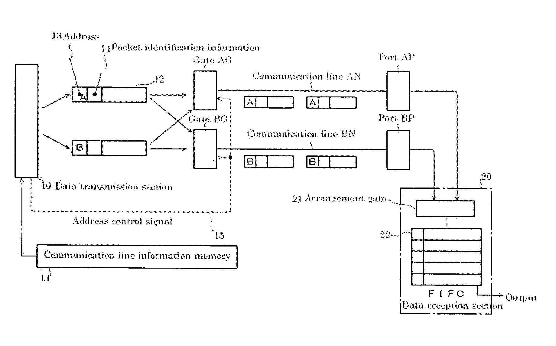
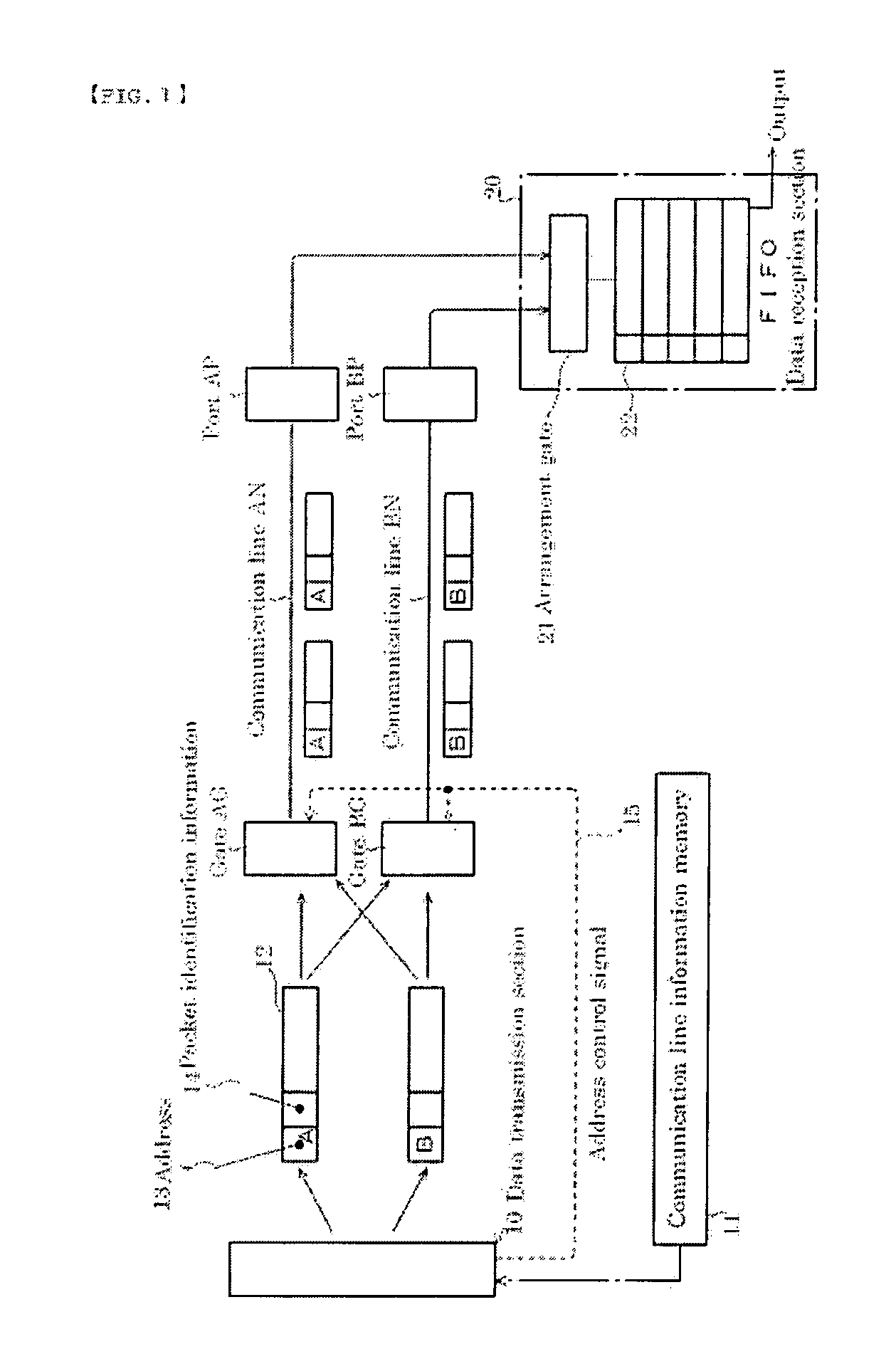
[0045]FIG. 1 is a block diagram showing an example of an image data communication apparatus.

[0046]A data transmission section 10 shown in FIG. 1 holds original image data to be transmitted. Accordingly, a not shown components such as image data generation unit, a storage unit, and a transmitter are provided in the data transmission section 10. The original image data mentioned here is data obtained by shooting an object with a TV camera and the like. That is, a TV camera or video equipment serves as the data generation unit. The entire or part of the original image data is temporarily stored in the data transmission section 10 and sequentially read out for output.

[0047]The original image data output from the data transmission section 10 is transmitted to a data reception section 20. The data transmission section 10 packetizes original image data for transmission. Each packet 12 includes a destination port address 13. Further, each packet 12 includes packet identification information...

example 2

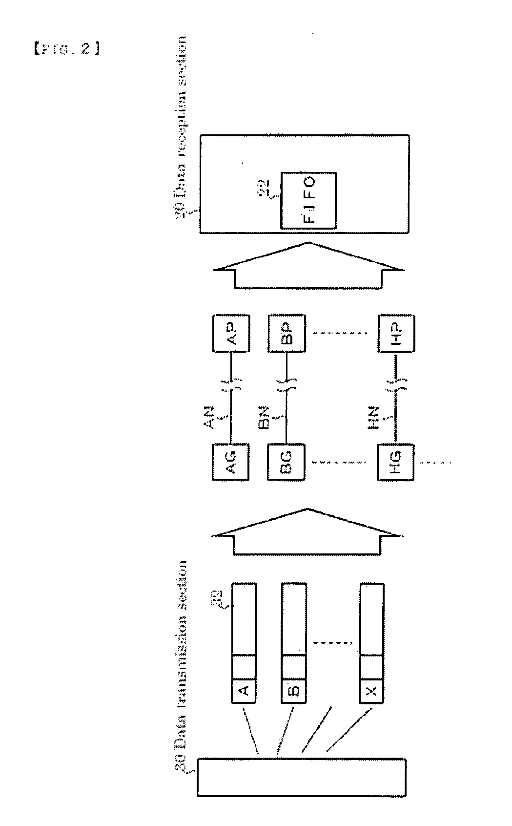
[0056]FIG. 2 is a block diagram showing another example of the present invention.

[0057]This block diagram simplifies content that overlaps between FIGS. 1 and 2. In the example shown in FIG. 1, two ADSL communication lines are used to secure a predetermined transmission capacity. In this example, a given plurality of communication lines are used to achieve the same object. A plurality of packets 32 are output from a data transmission section 30. These packets 32 are distributed to a plurality of communication lines AN to HN. It is assumed that substantially the same transmission rate is set in these transmission lines. In this example, all packets are output from the data transmission section 30 in the rearrangement order, i.e., in the order of [1], [2], [3], [4], [5], [6], . . . . The packets having identification information of [1], [2], [3], [4], [5], [6], . . . are serial / parallel converted to be supplied to gates AG, BG, CG, DG, EG and transmitted to the data reception section ...

example 3

[0059]FIG. 3 is a block diagram showing still another example of the present invention.

[0060]In this example, a packet 12 that includes only the packet identification information 14 is output from the data transmission section 10. The gates AG and BG acquire information concerning the communication line from the communication line information memory 11. In this example, two communication lines are provided. Control information stored in the communication line information memory 11 indicates a procedure of transmitting packets whose packet identification information indicates even number to the communication line AN and transmitting packets whose packet identification information indicates odd number to the communication line BN. The control information is supplied to the gates AG and BG. All the packets generated by the data transmission section 10 are distributed to respective communication lines according to the above procedure. Subsequent packet processing performed in the data r...


PUM


Abstract

Disclosed is an image data communication apparatus for achieving real-time transmission of image data such as one compatible with an extended definition television using a plurality of communication lines having a transmission capacity equivalent to an ADSL system at a time. The data communication apparatus includes a data transmission section 10, gates AG and BG, and a data reception section 20. The data transmission section 10 packetizes original image data to be transmitted and assigns, to each packet 12, identification information 14 by which one packet can be distinguished from another so as to output generated packets. The gates AG and BG refer to the identification information 14 to distribute the packets output from the data transmission section 10 to different communication lines AN and BN based on previously set conditions. The data reception section 20 refers to the identification information 14 to rearrange the packets transmitted thereto via the plurality of communication lines AN and BN in a predetermined order and reproduces the original image data.

Description

BACKGROUND OF THE INVENTION[0001]1. Field of the Invention[0002]The present invention relates to an image data communication apparatus that transmits high-quality image data such as a High-Vision™ image using a packet communication line.[0003]2. Description of the Related Art[0004]Packetization of television image data allows distribution of a TV broadcasting service via the Internet connection. For example, a TV broadcasting service using an NTSC system can be transmitted via a broadband Internet connection using an ADSL service. That is, it is only necessary to carry simple broadcasting equipment to a shooting site and it is possible to distribute a live broadcast from all corners of the country. This eliminates the need to provide expensive equipment for relay broadcast conventionally used. That is, it is considered that the method of real-time relay broadcast for TV broadcasting service will be remarkably changed. Such a technique is disclosed in, e.g., Jpn. Pat. Appln. Laid-Ope...

Claims


Application Information

Patent Timeline
IPC IPC(8): H04N7/173H04L69/14H04N21/235H04N21/238H04N21/2389H04N21/242H04N21/426H04N21/4385H04N21/6336H04N21/84
CPCH04L45/245H04L47/10H04L47/34H04L69/14H04N7/108H04N7/12Y02B60/33H04M11/062Y02D30/50
Inventor TANGO, HIROSHIIDE, HISAYUKIKAWAKAMI, KEITASHIMODAIRA, MICHISUKE
Owner FRONTIERS
Learn More