
Connected structural panels for buildings

a technology of connecting structural panels and buildings, applied in the direction of girders, walls, joists, etc., can solve the problems of high cost, waste of materials, and difficult handling of blocks and bricks on the building site, and achieve the effects of improving construction efficiency, reducing construction costs, and improving construction efficiency

Inactive Publication Date: 2008-08-21
HARLEY RESOURCES
View PDF31 Cites 23 Cited by
  • Summary
  • Abstract
  • Description
  • Claims
  • Application Information

AI Technical Summary

Benefits of technology

[0017]Another objective of the invention is to provide connected structural panels for buildings, which also makes it possible to divide the construction in a logical way according to its functional and architectural divisions, facilitating the joints between elements, installations and fittings.
[0050]In buildings, the structural panel system described herein is suitable for three-dimensional arrangements of modular panels that are efficient in resisting vertical loads, due to the small spans in buildings of social interest, and in supporting lateral loads, due to the density of walls in both directions.

Problems solved by technology

Even if pallets are used, blocks and bricks are not simple to handle on the building site.
They may be handled manually or using specialised machinery, which requires excessive labour and increases the cost.
They are fragile building elements, so their use is very wasteful.
The process involved in finishing a wall is slow, regardless of whether plaster or cement mortar is used, as it is necessary to wait several days before it can be worked on again.
This weakens them, it produces a lot of rubble, and it is necessary to cover the hole, which is slow and can lead to the appearance of cracks in the finished wall.
The cost of labour is high and it is in increasingly short supply.
The high demand for housing cannot be met by conventional building methods.
Severe weather conditions limit the time of year when building work can be carried out using conventional systems.

Method used


Image

  • Connected structural panels for buildings
  • Connected structural panels for buildings
  • Connected structural panels for buildings

Examples


Embodiment Construction

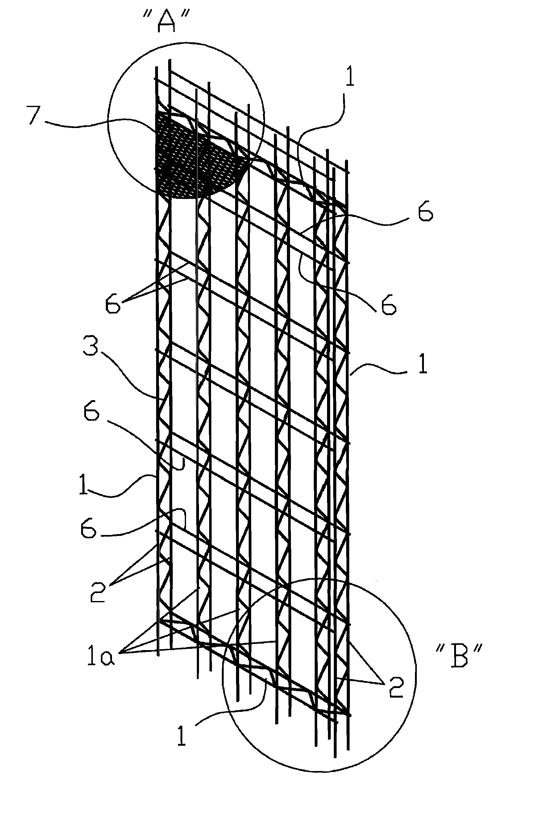
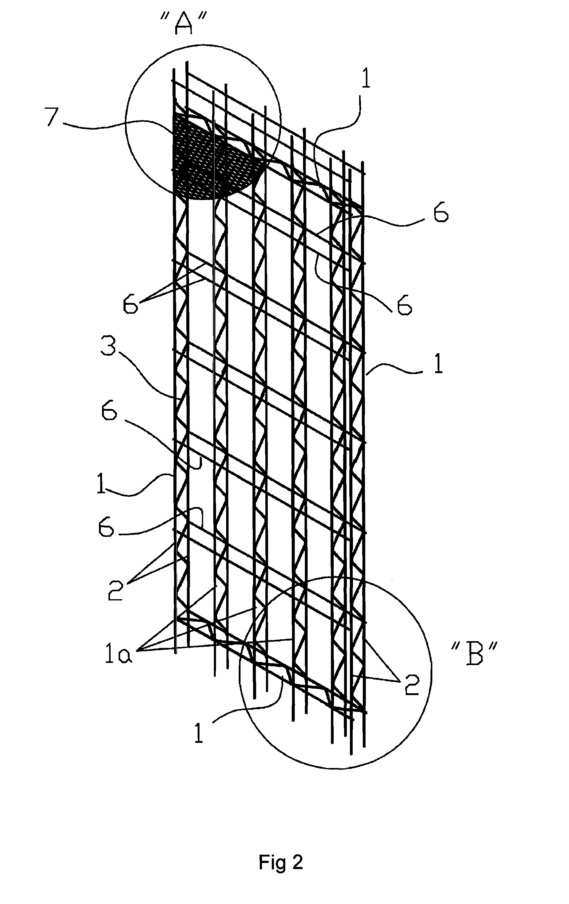
[0082]The characteristic details of the connected structural panels for buildings are clearly shown in the following description and in the illustrative drawings that are attached, which serve as reference marks to indicate the parts that are being referred to.

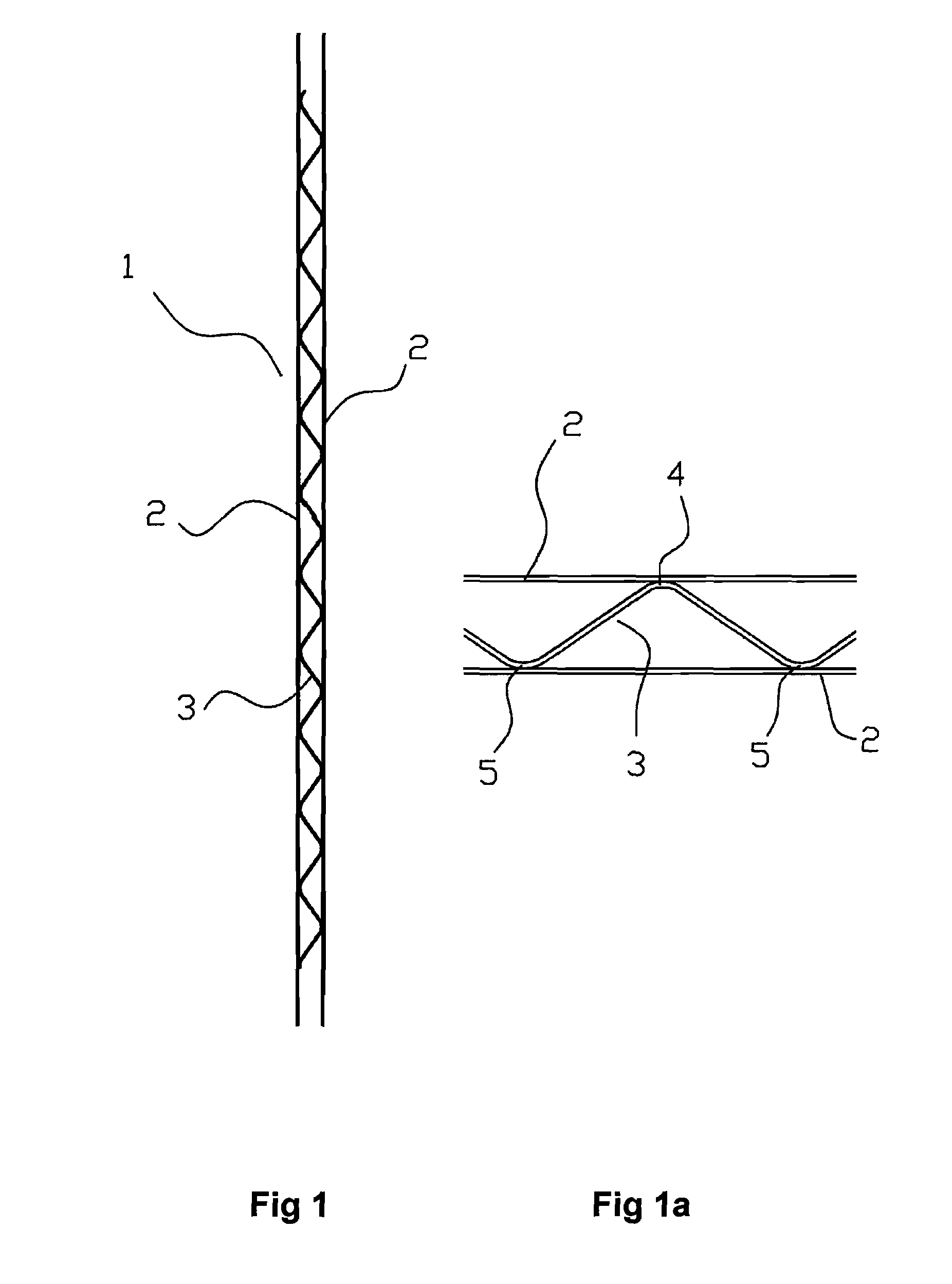
[0083]With reference to FIG. 1, it shows a side view of one of the trusses that form the structural panel for buildings. In said figure, the trusses 1 consist of a metal structure based on two parallel rods 2 that are tangentially joined to a zigzag rod 3 by its corresponding peaks and troughs.

[0084]With reference to FIG. 1a, it shows a side view of a portion of a truss 1 of the panel according to the present invention. In said figure, it can be observed that the zigzag rod 3 is tangentially joined to both the parallel rods 2, where the peaks 4 and troughs 5 are fixed to the corresponding parallel rod 2. The peaks and troughs 4 and 5 of the zigzag rod 2 have a longitudinal section that ensures a tangential joint with the paral...


PUM


Abstract

The present invention relates to the design, development and implementation of a building system using connected structural panels to form walls, floor slabs, stairs and other minor elements in buildings; characterised in that it is made up of a frame defined by peripheral trusses, wherein each truss consists of a metal structure based on two parallel rods tangentially joined to a zigzag rod by the corresponding peaks and troughs thereof; a plurality of vertical trusses thus formed are distributed equidistantly or not at a predetermined distance, acting as structural elements, and a plurality of horizontal and / or diagonal transversal rods are fastened to both the front and back sides distributed equidistantly or not at a predetermined distance as reinforcement elements to stiffen the panel, the assembly defining a hollow three-dimensional box; a tightened metal framework is joined to both the front and back sides as a means of support for the mortar that is applied to the front and back sides as a covering to form the wall.

Description

[0001]This application claims the benefit of Spanish Application No. 200700383, filed Feb. 13, 2007, the entire disclosure of which is incorporated by reference.FIELD OF THE INVENTION[0002]The present invention relates to the construction sector, in particular to the structural elements used in a prefabricated building system; more specifically it relates to the design, development and implementation of a building system using connected structural panels to form walls, stairs and other minor elements in buildings.BACKGROUND OF THE INVENTION[0003]The traditional building method that is currently used is always based on the use of different types, shapes and sizes of bricks or lightweight concrete blocks in different thicknesses and sizes.[0004]This building method has numerous disadvantages, which include:[0005]Even if pallets are used, blocks and bricks are not simple to handle on the building site. They may be handled manually or using specialised machinery, which requires excessiv...

Claims


Application Information

Patent Timeline
Patent Type & Authority Applications(United States)
IPC IPC(8): E04C3/04E04B1/19E04C2/38E06B1/04
CPCE04C2/044E04B2/845E04B1/16E04B2/84E04C2/384
Inventor GONZALEZ, FRANCISCO VERA
Owner HARLEY RESOURCES
Learn More