
Balun transformer, mounting structure of balun transformer, and electronic apparatus having built-in mounting structure

a technology of mounting structure and balun transformer, which is applied in the direction of inductance, continuous variable inductance/transformer, one-port network, etc., can solve the problems of difficulty in broadband, degradation of amplitude balance characteristics and phase balance characteristics, etc., and achieve low loss and large coupling coefficient

Inactive Publication Date: 2008-08-21
SONY CORP
View PDF15 Cites 72 Cited by
  • Summary
  • Abstract
  • Description
  • Claims
  • Application Information

AI Technical Summary

Benefits of technology

[0030]The magnetic ferrite, a common mode noise filter and a chip transformer using the magnetic ferrite can realize magnetic ferrite which has a low loss in a high frequency band and can be baked together with...

Problems solved by technology

Since the balance level of the balun transformer is lowered, there arises a problem of degraded amplitude balance characteristics and phase balance characteristics.
Therefore, when an unbalanced signal is input to the unbalanced signal input terminal Port1, balanced signal outputs at the balanced input / output terminals Port2 and Port3 have an electrical phase difference, posing a problem of difficulty of a broadband.

Method used


Image

  • Balun transformer, mounting structure of balun transformer, and electronic apparatus having built-in mounting structure
  • Balun transformer, mounting structure of balun transformer, and electronic apparatus having built-in mounting structure
  • Balun transformer, mounting structure of balun transformer, and electronic apparatus having built-in mounting structure

Examples


Embodiment Construction

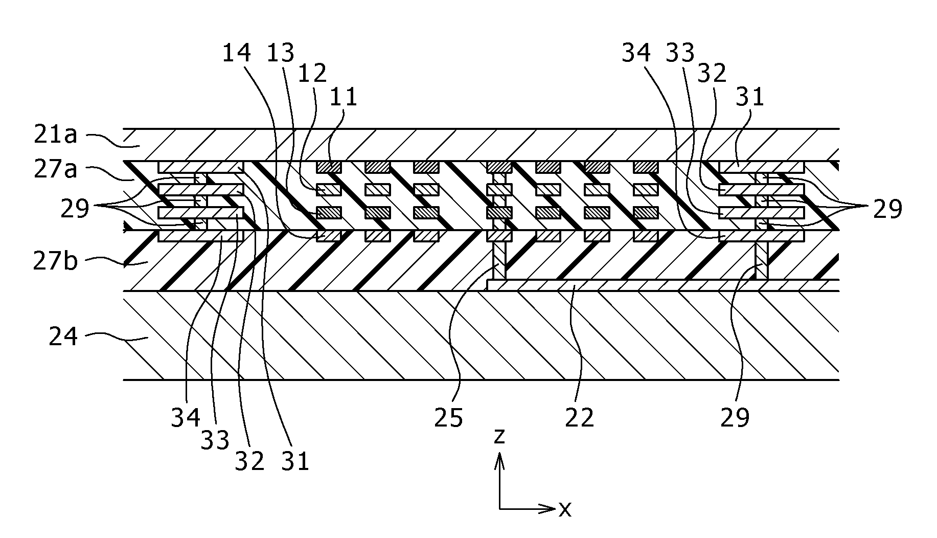
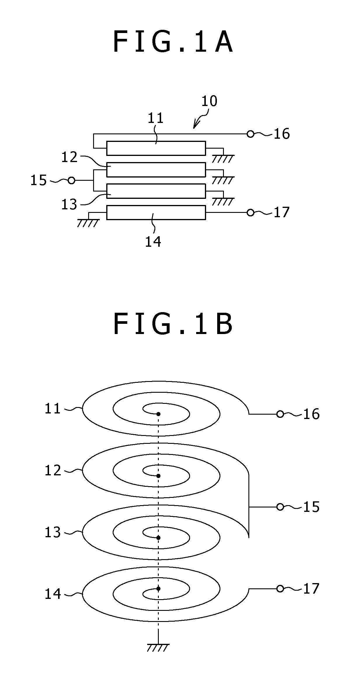
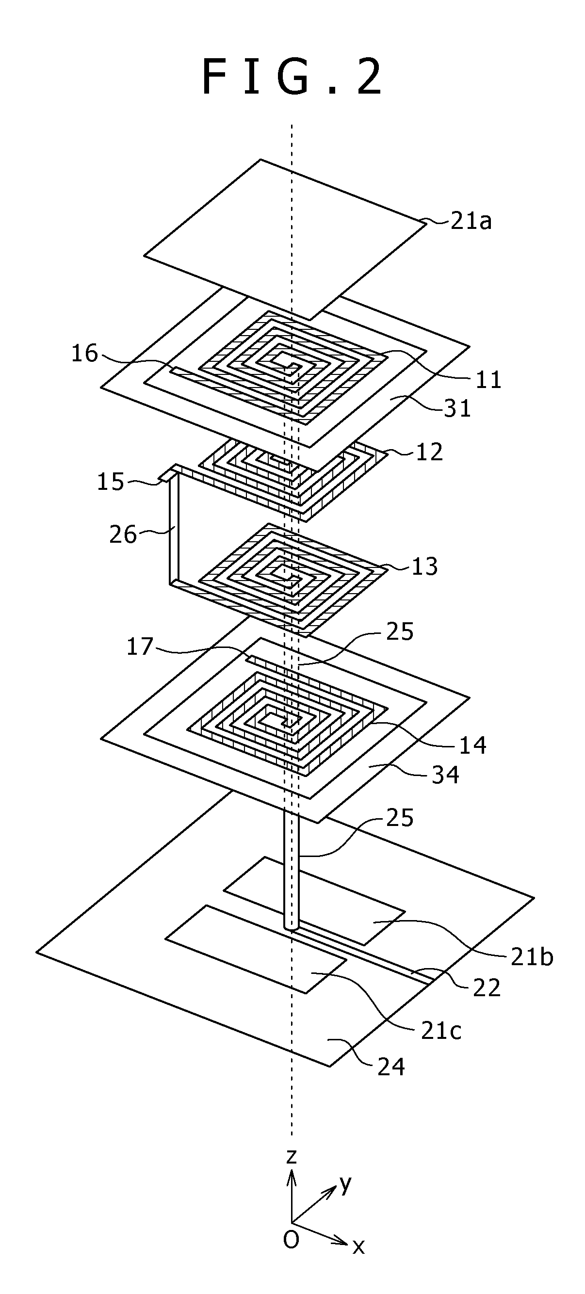
[0055]In a balun transformer according to an embodiment of the present invention, it is preferable that first to third layer coils are wound in the same direction, and a fourth layer coil is wound in an opposite direction to the same direction. The first to third layer coils are wound in the same direction, the second and third layer coils are connected in parallel, with an unbalanced signal being input / output to / from a common terminal, and the fourth layer coil is wound in the opposite direction to the above-described same direction. Accordingly, magnetic fields generated by the second and third layer coils are enhanced so that electromagnetic coupling between the first and fourth layer coils becomes strong. Therefore, as an unbalanced signal is input to the common terminal, a first balanced signal output from the other end of the first layer coil and a second balanced signal output from the other end of the fourth layer coil have high output levels.

[0056]The winding direction of t...


PUM


Abstract

There is provided a balun transformer, in which first to fourth layer coils are stacked and coupled magnetically; one end of each coil of the first to fourth layer coils is grounded; the second and third layer coils are connected in parallel, an unbalanced signal is input / output to / from a common terminal of the second and third layer coils; a first balanced signal is input / output to / from the other end of the first layer coil; and a second balanced signal is input / output to / from the other end of the fourth layer coil.

Description

BACKGROUND OF THE INVENTION[0001]1. Field of the Invention[0002]The present invention relates to a balun transformer used for a balance-unbalance signal converter for converting balanced signals into an unbalanced signal and vice versa, a phase converter and the like, and more particularly to a compact, broadband balun transformer and a mounting structure for a balun transformer and an electronic apparatus having a built-in mounting structure.[0003]2. Description of Related Art[0004]A balun transformer is used, for example, as a converter for converting balanced signals into an unbalanced signal or vice versa. Balanced lines have a pair of signal lines, and a balanced signal is propagated as a potential difference between paired signal lines. An unbalanced line is used for an unbalanced signal propagated as a potential at one signal line relative to a ground potential. As an unbalanced signal is input to an unbalanced terminal of a balun transformer, two balanced signals having a ph...

Claims


Application Information

Patent Timeline
IPC IPC(8): H01F27/32
CPCH01F17/0013H01F19/06H03H2001/0085H03H7/42H01F2017/0066
Inventor MUTO, AKIRA
Owner SONY CORP
Learn More