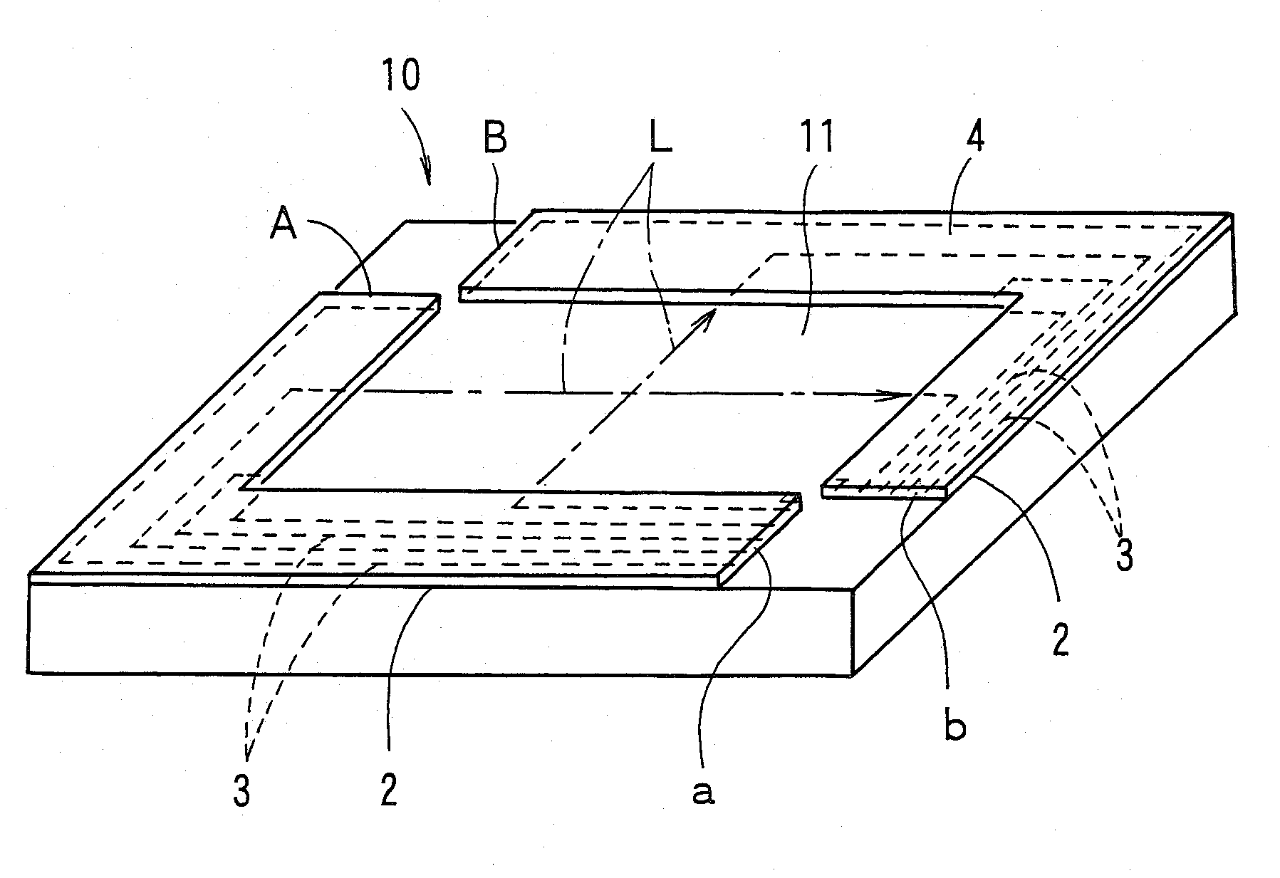
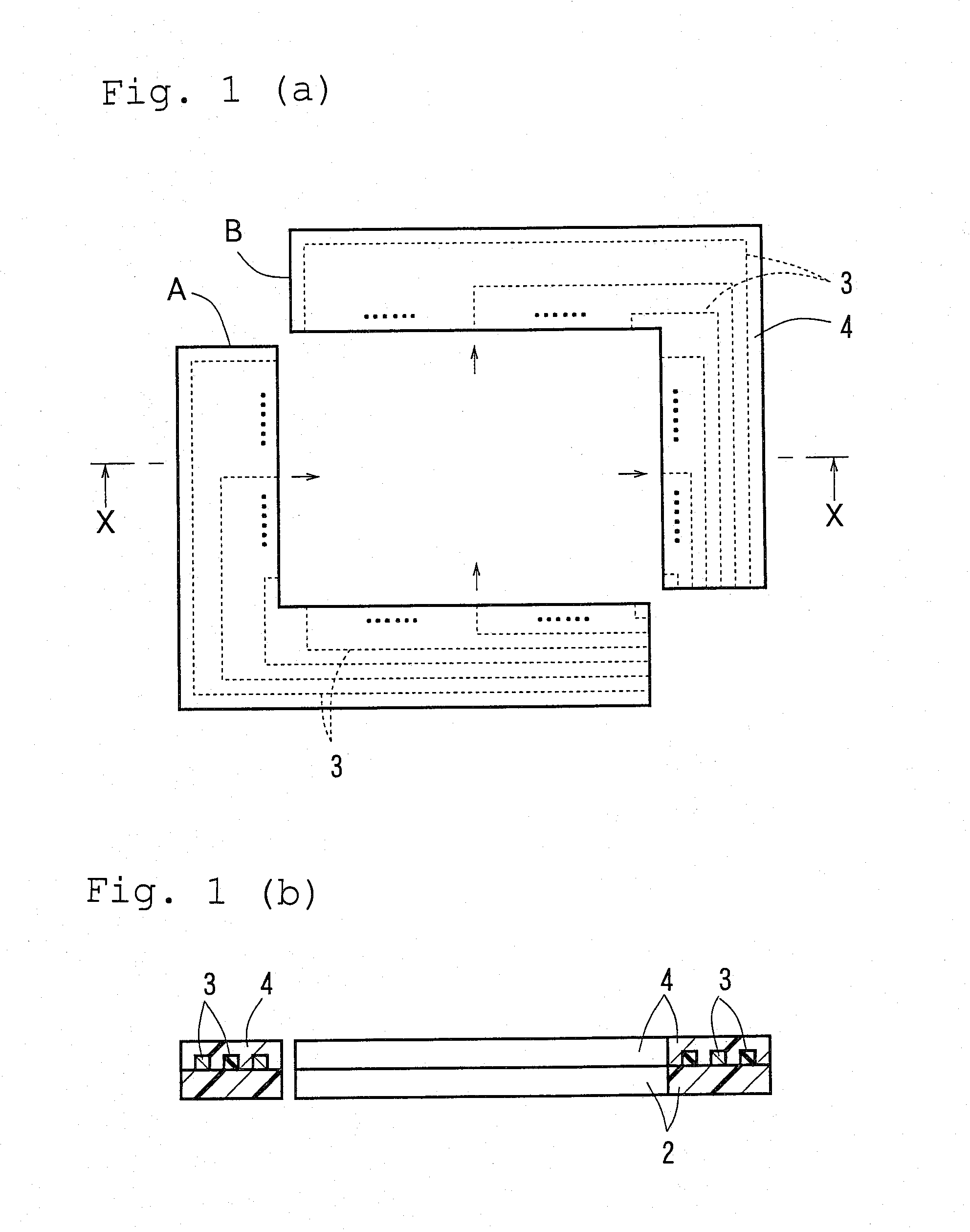
Optical waveguide for touch panel
- Summary
- Abstract
- Description
- Claims
- Application Information
AI Technical Summary
Benefits of technology
Problems solved by technology
Method used
Image

Examples
example 1
Material for Formation of Under-Cladding Layer and Over-Cladding Layer
[0064]A material for formation of an under-cladding layer and an over-cladding layer was prepared by mixing 35 parts by weight of bisphenoxyethanolfluorene glycidyl ether (component A) represented by the following general formula (1), 40 parts by weight of (3′-4′-Epoxycyclohexane)methyl 3′-4′-Epoxycyclohexyl-carboxylate (an alicyclic epoxy CELLOXIDE 2021P manufactured by Daicel Chemical Industries, Ltd.) (component B), 25 parts by weight of an alicyclic epoxy resin having a cyclohexene oxide skeleton (CELLOXIDE 2081 manufactured by Daicel Chemical Industries, Ltd.) (component C), and 2 parts by weight of a 50% propione carbonate solution of 4,4′-bis[di(β-hydroxyethoxy)phenylsulfinio]phenylsulfide bishexafluoroantimonate (component D).
wherein R1 to R6 are hydrogen atoms, and n=1.
Material for Formation of Cores
[0065]A material for formation of cores was prepared by dissolving 70 parts by weight of the aforementioned...
PUM
 Abstract
Description
Claims
Application Information
 - Generate Ideas
- Intellectual Property
- Life Sciences
- Materials
- Tech Scout
- Unparalleled Data Quality
- Higher Quality Content
- 60% Fewer Hallucinations
Browse by: Latest US Patents, China's latest patents, Technical Efficacy Thesaurus, Application Domain, Technology Topic, Popular Technical Reports.
© 2025 PatSnap. All rights reserved.Legal|Privacy policy|Modern Slavery Act Transparency Statement|Sitemap|About US| Contact US: help@patsnap.com