Temperature measurement system

a temperature measurement and temperature technology, applied in the field of temperature measurement systems, can solve the problems of inability to integrate the temperature, the best possible control of temperature is limited, and the cooling effect is not precis

Inactive Publication Date: 2008-08-21
ROSEMOUNT AEROSPACE
View PDF27 Cites 21 Cited by
  • Summary
  • Abstract
  • Description
  • Claims
  • Application Information

AI Technical Summary

Benefits of technology

[0019]In accordance with yet another aspect of the invention, the temperature sensor can include at least one thermocouple. The thermocouple can include a second bimetallic member, or alternatively the bimetallic member can serve as both the thermocouple and the means for biasing. It is envisioned that the thermocouple can be of any of the following...

Problems solved by technology

Unfortunately, because of the design of modern continuous casting machines, the best possible control of temperature is limited under the state of the art.
However, no successful attempts have been made to integrate that temperature to a predetermined curve such as an ideal curve, and imprecise cooling is the result.
This is due in large part to the inability of traditional measurement systems to make accurate temperature readings in the casting environment, which includes temperature diverse flows of cooling fluids, gases, heated steam, other impurities, and metal in various stages of the liquid to solid transition.
Breakout is a major problem that occurs when the thin shell of the strand of material breaks, allowing the still-molten metal inside the strand to spill out and foul the casting system, requiring an expensive shutdown.
Often, breakout is due to too high a withdrawal rate, resulting in the shell not having enough time to solidify to the required thickness.
Alternatively, breakout can be due to the metal being too hot, which means that final solidification takes place below the straightening ro...

Method used


Image

  • Temperature measurement system
  • Temperature measurement system
  • Temperature measurement system

Examples


Embodiment Construction

[0036]Reference will now be made in detail to the present preferred embodiments of the invention, examples of which are illustrated in the accompanying drawings. The temperature measurement system and corresponding parts of the invention will be described in conjunction with the detailed description of the system.

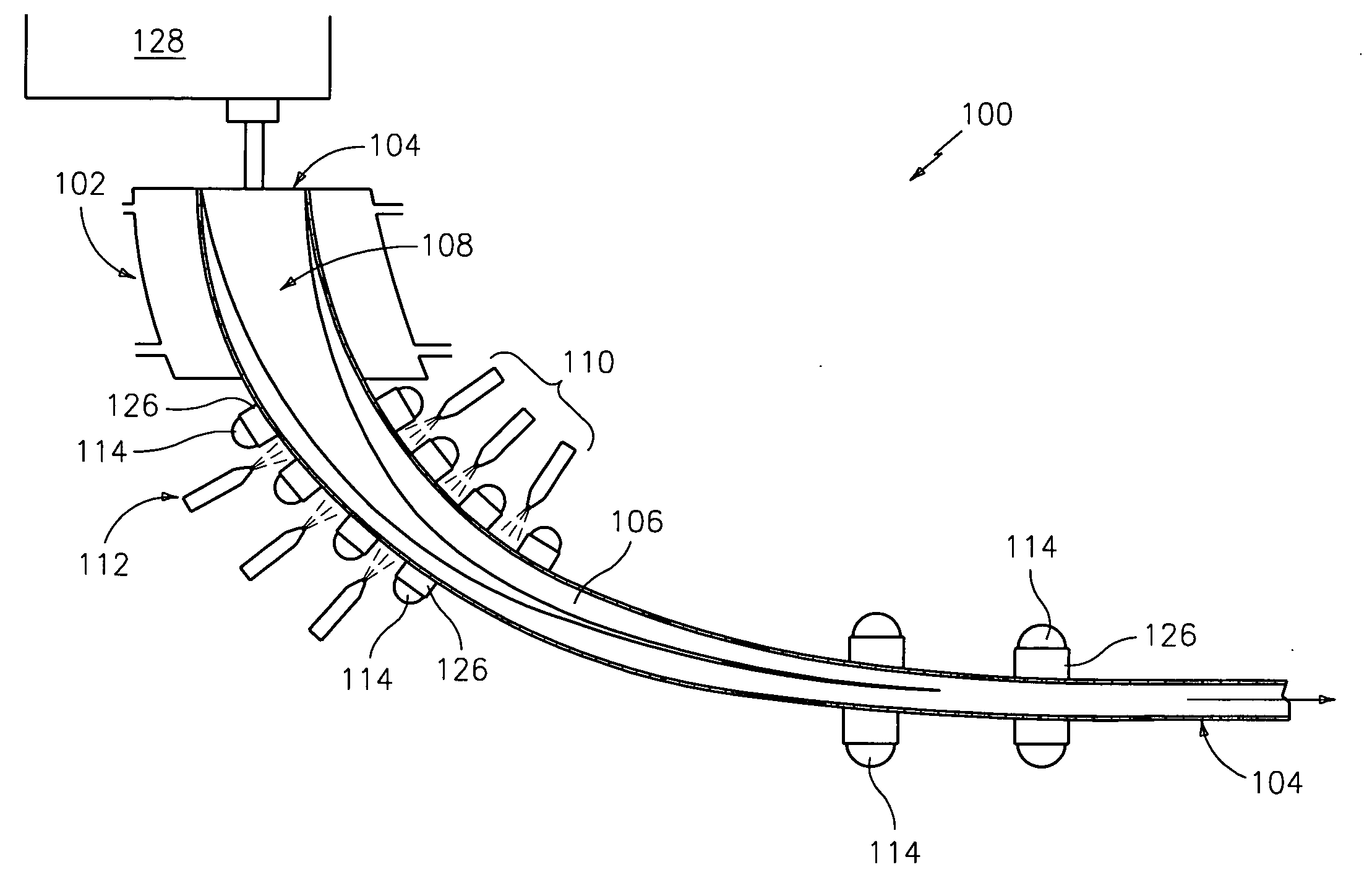
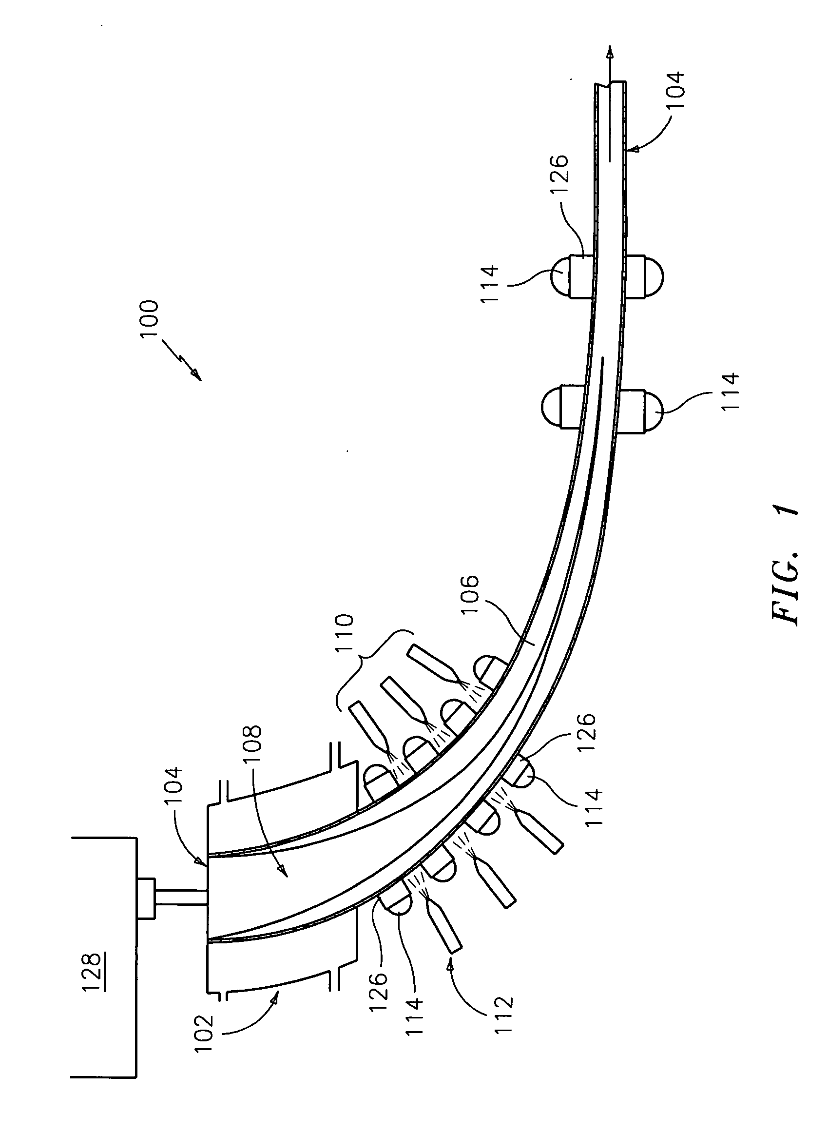
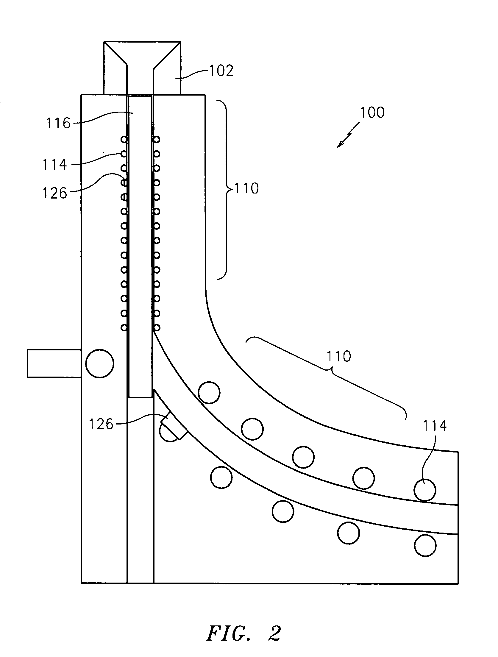
[0037]The devices and methods presented herein may be used for measuring the operating temperatures of processes. The present invention is particularly suited for measuring temperatures in processes which require extension and subsequent retraction of a temperature sensor, such as when measuring the temperature of a slab or strand of metal being continuously cast while avoiding damaging interference with a structure, such as a dummy bar, moving back and forth between subsequent slabs or strands.

[0038]In accordance with the invention, a continuous casting system is provided including a mold for dispensing a strand of metal, a secondary cooling region downstream from the mold...


PUM

PropertyMeasurementUnit
Temperatureaaaaaaaaaa
Lengthaaaaaaaaaa
Electrical resistanceaaaaaaaaaa

Abstract

The invention provides a temperature measurement system including a temperature sensor and means for biasing the temperature sensor in the direction of a thermal energy source in response to receiving thermal energy from the source. The invention also provides a continuous casting system including at least one temperature sensor disposed in the secondary cooling region and means for biasing the temperature sensor in the direction of the strand of metal in response to receiving thermal energy from the strand of metal.

Description

BACKGROUND OF THE INVENTION[0001]1. Field of the Invention[0002]The present invention relates to a temperature measurement system for monitoring the operating temperatures in a process. Particularly, the present invention is directed to a temperature measurement system wherein the temperature sensor is biased in the direction of thermal energy emitted by the body to be measured.[0003]2. Description of Related Art[0004]A variety of temperature measurement devices are known in the art for monitoring temperatures within a process. Of such devices, many are directed to measuring the temperature of metal being cast in a continuous casting process.[0005]In a continuous casting machine (or “caster”), molten metal is poured into a cooled copper faced mold that controls the physical width and thickness of the finished product. Metal exits the mold in the form of a strand or slab having a thin shell of solidified metal with a core of molten metal. The strand continues into a secondary cooling...

Claims


Application Information

Patent Timeline
IPC IPC(8): G01K1/00B22D30/00G01K7/02
CPCB22D11/225G01K13/00G01K1/146
Inventor MYHRE, DOUGLAS C.
Owner ROSEMOUNT AEROSPACE
Why Eureka
Try Eureka