Transceiver module

a technology of transceiver and receiver, which is applied in the direction of optical elements, coupling device connections, instruments, etc., can solve the problems of lack of generality and high cost of communication devices for transmitting or receiving optical signals such as the transmitter and the receiver mentioned above, and achieve the effect of satisfying demand and moderate cos

Inactive Publication Date: 2008-08-21
FUJITSU COMPONENENT LTD
View PDF3 Cites 49 Cited by
  • Summary
  • Abstract
  • Description
  • Claims
  • Application Information

AI Technical Summary

Benefits of technology

[0030]In accordance with the invention, it is possible to provide a transceiver module that is capable of performing a high-rate communication, and satisfies the demand at a moderate cost in a case where short distance communication is enough for transmitting or receiving signals.

Problems solved by technology

However, there is a problem that a communication device for transmitting or receiving optical signals such as the transmitter and the receiver mentioned above is expensive and lacks in generality compared to a communication device for transmitting or receiving electrical signals.

Method used


Image

  • Transceiver module
  • Transceiver module
  • Transceiver module

Examples


first embodiment

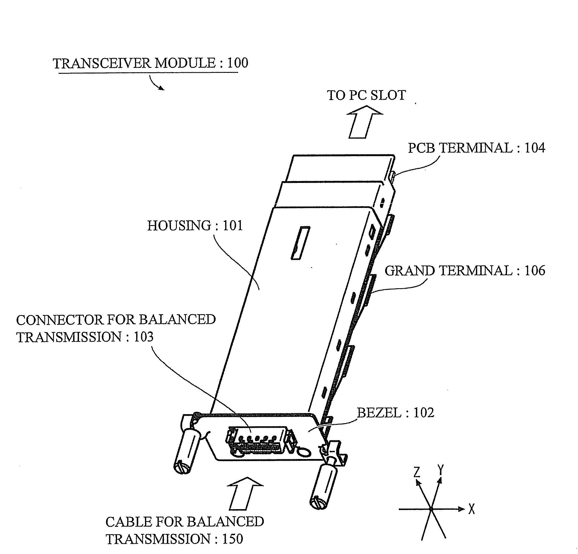
[0056]A detail description will be given of a transceiver module 100 in accordance with a first embodiment of the present invention, with reference to the following drawings. The first embodiment relates, in particular, to a transceiver module compliant with an Ethernet (registered trademark) having a max transfer rate at 10 Gbps. The transceiver module can be coupled to a cable 150 for balanced transmission mentioned later (referring to FIG. 5) and allows sending or receiving data between information-processing devices such as a server device, a network communication device (host device) or the like. However, this invention is not limited to these mentioned above and is susceptible of modification, variation and change without departing from the proper and fair meaning.

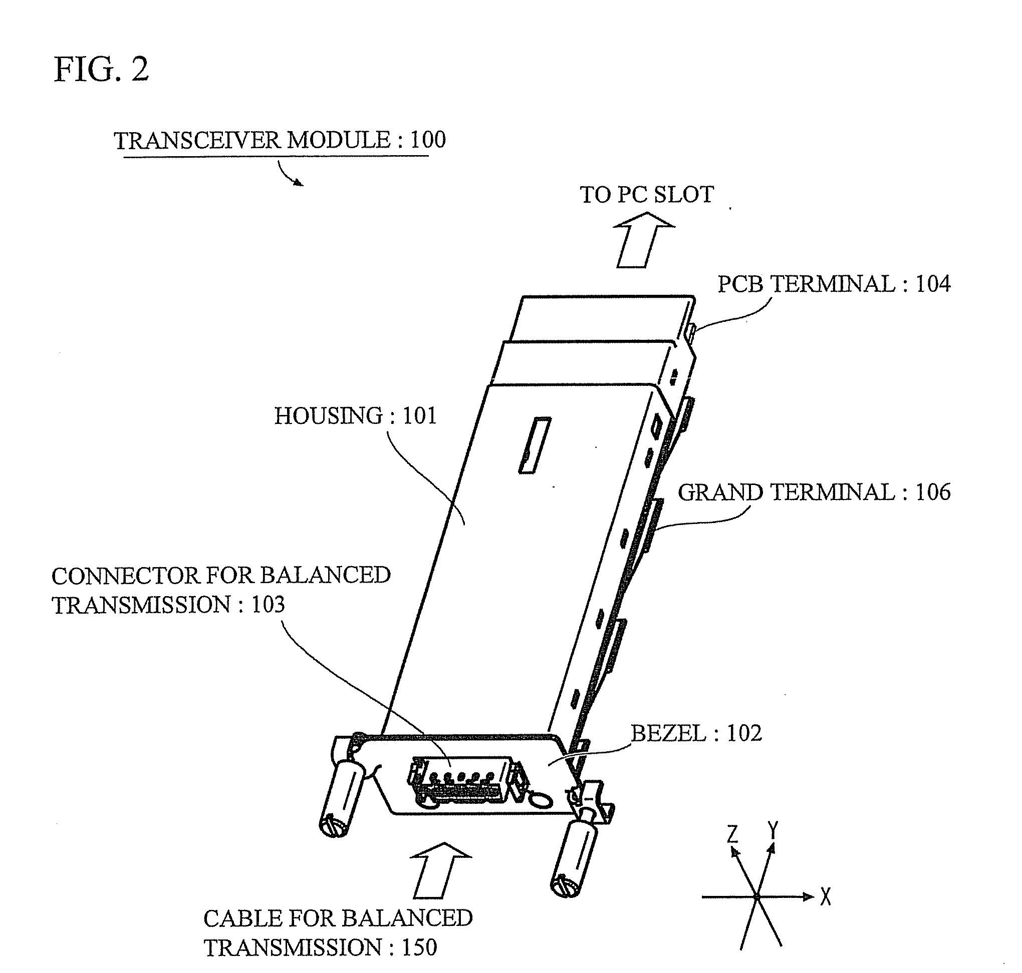
[0057]FIG. 2 illustrates a perspective view of a schematic exterior of the transceiver module 100 in accordance with the first embodiment. As shown in FIG. 2, the transceiver module 100 has a housing 101, a bezel 102...

second embodiment

[0095]Next, a detail description will be given of a second embodiment with reference to following drawings. Hereinafter, the same components and configurations as those of the first embodiment have the same reference numerals and a detailed explanation will be omitted. In addition, unspecified configuration is same as in the first embodiment.

[0096]In the first embodiment, only electrical signals are intended. In contrast, both of electrical signals and light signals are intended in the second embodiment. In addition, the structure of a transceiver module 200 is as same as that of the transceiver module 100. A detail description is omitted. A detail description will be given of a circuit configuration that is characteristic part of the second embodiment.

[0097]FIG. 12 illustrates a block diagram showing a circuit configuration of the transceiver module 200 in accordance with the second embodiment. As shown in FIG. 12, the transceiver module 200 in accordance with the embodiment has th...

third embodiment

[0109]A detail description will be given of a third embodiment of the invention with reference to following drawings. Hereinafter, the same components and configurations as those of the first embodiment or the second embodiment have the same reference numerals and a detailed explanation will be omitted. In addition, unspecified configuration is same as in the first embodiment or the second embodiment.

[0110]FIG. 15 illustrates a perspective view of a schematic exterior of a transceiver module 300 in accordance with the third embodiment. As shown in FIG. 15, the transceiver module 300 has the same structure as the transceiver module 100 in accordance with the first embodiment and has a lever for detachment 301 and a latch 302.

[0111]The latch 302 locks the transceiver module 300 at the host device, when the transceiver module 300 is attached to a slot of the host device and the latch 302 is engaged with a groove of the rail of the slot. The latch 302 prevents an unconsidered detachment...


PUM


Abstract

The object is to provide a transceiver module that is capable of performing a high-rate communication, and satisfies the demand at a moderate cost in a case where short distance communication is enough for transmitting or receiving signals.The transceiver module has a Re-timer 11, a control portion 12, a reference clock generating portion 13, a power portion 14 and a CX4 interface 15. The Re-timer 11 is coupled to a transceiver portion (Tx / Rx) 21 through an XAUI (10 Gigabit Media Independent Interface) interface 22, and is coupled to other component that is coupled to one end of a cable 150 for balanced transmission through the CX4 (10GBASE-CX4) interface 15.

Description

[0001]This application is a divisional of U.S. application Ser. No. 11 / 635,545, filed Dec. 8, 2006 which also is a continuing application, filed under 35 U.S.C. §111 (a), of International Application PCT / 2004 / 008335, filed Jun. 15, 2004, the entire contents of which are incorporated herein by reference.TECHNICAL FIELD[0002]This invention generally relates to a transceiver module, and in particular, relates to a transceiver module that is compliant with an Ethernet (registered trademark) having a max transfer rate at 10 Gbps.BACKGROUND ART[0003]Recently, there is a demand for further improvement of a transmission rate and a further extension of transmission distance because of a development of information society. A signal transferred on a network is changing from electricity to light.[0004]There is an optical transceiver module disclosed in Japanese Patent Application Publication No. 2002-328269, as a communication device that uses an optical signal, has large capacity, and performs...

Claims


Application Information

Patent Timeline
Patent Type & Authority Applications(United States)
IPC IPC(8): G02B6/36G02B6/42G06F3/00H04B1/38H04B1/40
CPCH01R12/721H04B10/40H04B1/406H01R31/065
Inventor TAKIZAWA, SHIGEYUKIDAIKUHARA, OSAMUITO, TAKESHI
Owner FUJITSU COMPONENENT LTD
Why Eureka
Try Eureka