

Camera system
- Summary
- Abstract
- Description
- Claims
- Application Information
AI Technical Summary
Benefits of technology
Problems solved by technology
Method used
Image

Examples
embodiment 1
[1. Configuration of Camera System]
[0018][1-1. Overview of Camera System]
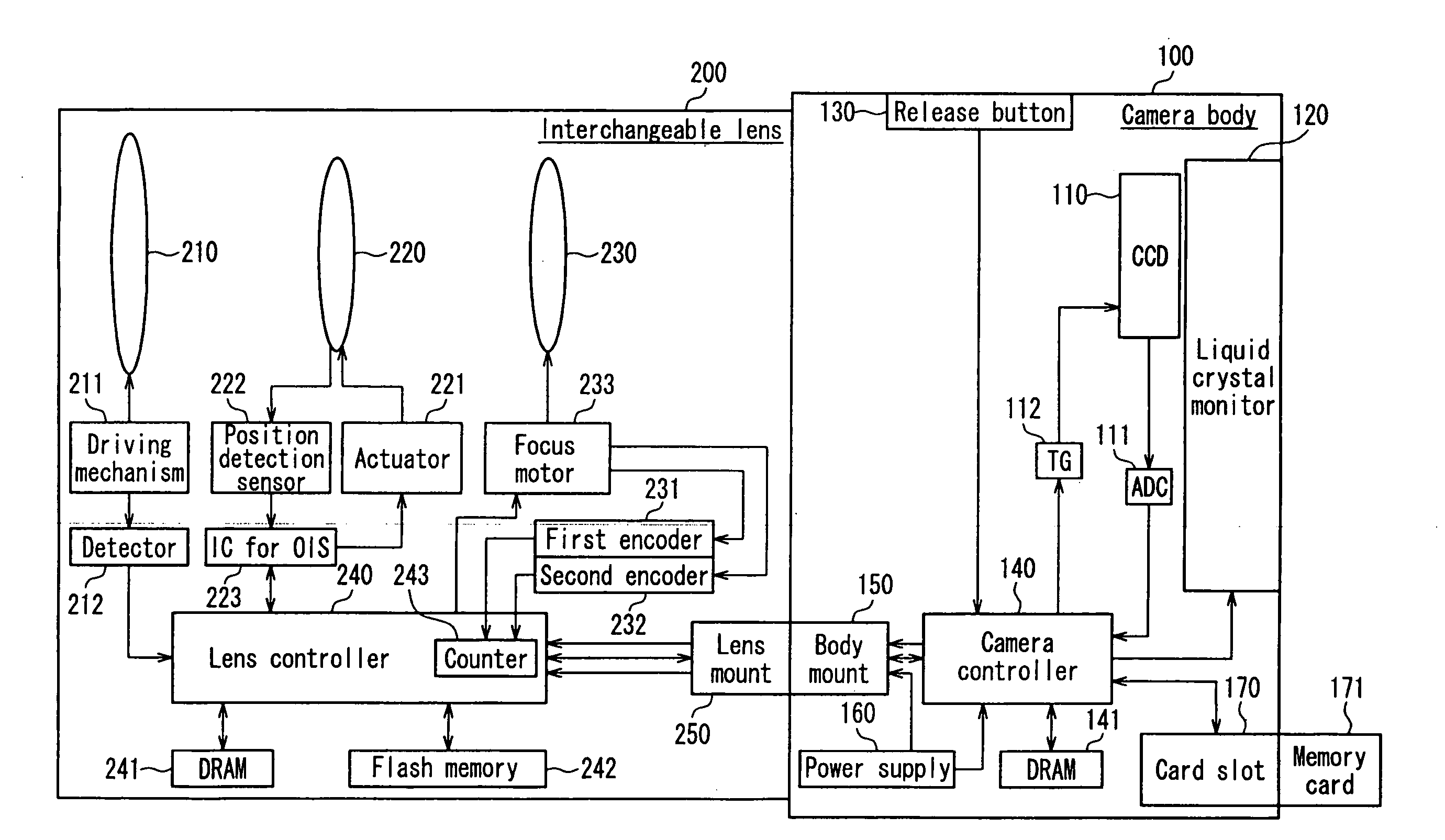
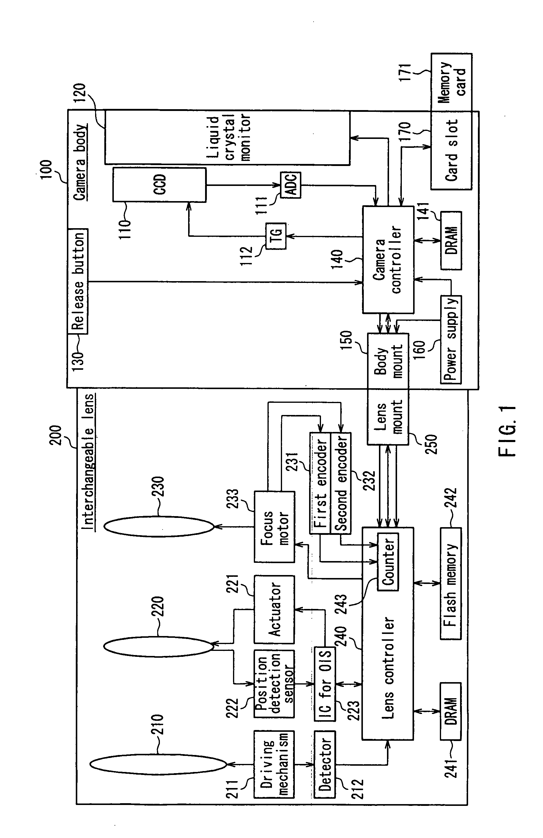
[0019]FIG. 1 is a block diagram showing the configuration of a camera system 1 according to Embodiment 1 of the present invention. The camera system 1 includes a camera body 100 and an interchangeable lens 200 that can be attached to or detached from the camera body 100. The camera system 1 is capable of an autofocus operation with a contrast system based on image data generated in a CCD (charge coupled device) image sensor 110. The present invention was made in order to perform an autofocus operation with a contrast system at higher accuracy in a camera system with an interchangeable lens as described in Embodiment 1.
[0020][1-2. Configuration of Camera Body]
[0021]The camera body 100 includes the CCD image sensor 110, a liquid crystal monitor 120, a camera controller 140, a body mount 150, a power supply 160 and a card slot 170.
[0022]The camera controller 140 controls an entire camera system 1 including the CCD...
embodiment 2
[0080]As described above, in Embodiment 1, the exposure synchronizing signal of the CCD image sensor 110 has been used as the timing signal generated by the camera controller 140. In contrast, in Embodiment 2, a vertical synchronizing signal of the CCD image sensor 110 is used as the timing signal generated by the camera controller 140. It should be noted that a camera system according to Embodiment 2 of the present invention has a similar configuration to the camera system 1 according to Embodiment 1 and thus will be described with reference to the block diagram shown in FIG. 1.
[0081]FIG. 5 is a timing chart in an autofocus operation with a contrast system of the camera system 1 according to Embodiment 2.
[0082]As shown in FIG. 5(a), the camera controller 140 sends a vertical synchronizing signal both to the timing generator 112 and to the lens controller 240.
[0083]As shown in FIG. 5(b), the CCD image sensor 110 generates image data for calculating an AF evaluation value in synchron...
embodiment 3
[0088]Although the imaging device has been formed of the CCD image sensor 110 in Embodiment 1 of the present invention, it also may be formed of a MOS (metal oxide semiconductor) image sensor. Unlike the CCD image sensor, the MOS image sensor has varied exposure timings within a single screen. Thus, it is necessary to make the AF evaluation value and the positional information of the focus lens 230 correspond to each other, taking this into consideration. Thus, in the case of mounting the MOS image sensor, it is desired to capture a delay time of the exposure timings within a single screen (hereinafter, referred to as an exposure delay time, for the sake of convenience) and obtain the positional information of the focus lens 230 in synchronization with the exposure delay time.
[0089]Incidentally, the camera system including the MOS image sensor is equivalent to a configuration including the MOS image sensor instead of the CCD image sensor 110 in FIG. 1. Accordingly, the detailed desc...
PUM
 Abstract
Description
Claims
Application Information