Power Source Arrangement For Multiple-Target Sputtering System

a power source arrangement and sputtering technology, applied in the field of sputtering technology, can solve the problems of difficult control of magnetic lines, difficult confinement of plasma, difficult to confine plasma to a small area in front of the target, etc., and achieve the effect of reducing the cycling of substrates in the sputtering chamber

Inactive Publication Date: 2008-08-28
INTEVAC
View PDF25 Cites 41 Cited by
  • Summary
  • Abstract
  • Description
  • Claims
  • Application Information

AI Technical Summary

Benefits of technology

[0012]Embodiments of the present invention provide a system that enhances control over the plasma confinement. Embodiments of the present invention also provide a system that reduces cycling of substrates in sputtering chambers. Embodiments of the invention enable power and control of multiple targets in a sputtering system in a cost effective and space conserving manner.
[0013]In one aspect of the invention, plasma confinement is improved by using a conductive shield. In a further aspect of the invention, plasma confinement is further improved by incorporating magnets in the conductive shield.
[0014]In one aspect of the invention, cycling of substrates in sputtering chambers is reduced by having multiple-materials targets in each chamber. In one aspect of the invention, a single power source is multiplexed to power several sputtering targets simultaneously. According to an aspect of the invention, a power supply arrangement for concurrently powering multiple sputtering sources is provided, comprising, a DC power supply; a charge accumulator coupled to the power supply; a plurality of power delivery switches, each coupled between the charge accumulator and a respective one of the multiple sputtering sources; and a controller activating each of the power delivery switches to individually control the amount of power delivered from the charge accumulator to each of the multiple sputtering sources. The charge accumulator may comprise a capacitor. The charge accumulator may comprise a plurality of capacitors, each coupled to one of the power delivery switches. The power supply arrangement may further comprise a plurality of charging switches, each coupled between the power supply and one of the plurality of capacitors. The controller may comprise a plurality of feedback circuits, each coupled to one of the power delivery switches. Each of the plurality of feedback circuits may further comprise arc detection circuit. The power supply arrangement may further comprise a plurality of discharge paths, each coupled one of the sputtering sources. Each of the a plurality of discharge paths may comprise a positive potential node. The controller may comprise a plurality of control circuits, each coupled to one of the power delivery switches.

Problems solved by technology

However, when the target material 130 has magnetic permeability, it is difficult to control the magnetic lines.
Consequently, plasma confinement becomes difficult, especially when the target is small.
That is, it is difficult to confine the plasma to a small area in front of the target.

Method used


Image

  • Power Source Arrangement For Multiple-Target Sputtering System
  • Power Source Arrangement For Multiple-Target Sputtering System
  • Power Source Arrangement For Multiple-Target Sputtering System

Examples


Embodiment Construction

[0035]Various embodiments of the invention are generally directed to a system for sputtering layers of different materials on a substrate, such as a magnetic recordable media. The system may employ several sputtering chambers, each having a sputtering magnetron arrangement for several targets, or targets having several different materials. A metallic shield is provided between the target and the substrate. Magnets may be incorporated into the shield to assist in controlling the plasma confinement.

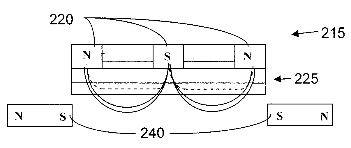
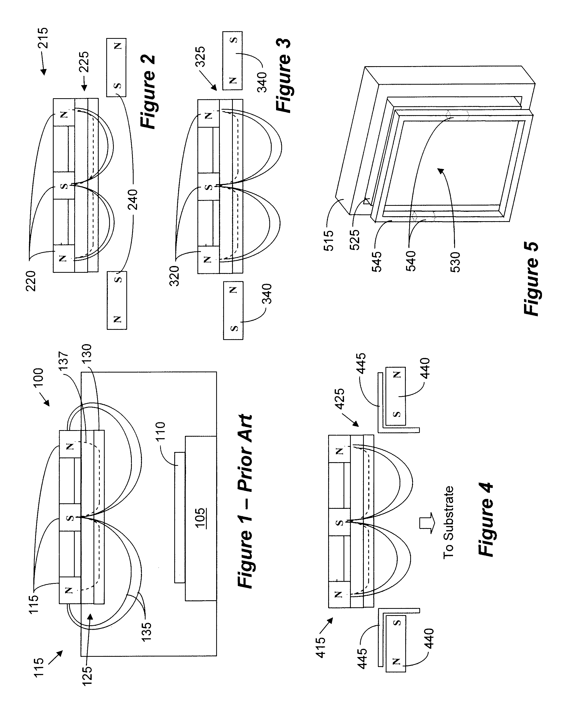
[0036]FIG. 2 is a conceptual diagram showing a magnetron having enhanced plasma confinement according to an embodiment of the invention. In the embodiment of FIG. 2, the same magnetron 215 as shown in FIG. 1 is used. However, magnets 240 have been added at a location extending beyond the front face of the target 225. In this configuration the poles of the magnets 240 are arranged so as to “pull” the magnetic lines at the outer periphery of the target, so as to cause the lines to assume a pa...


PUM

PropertyMeasurementUnit
poweraaaaaaaaaa
impedanceaaaaaaaaaa
phaseaaaaaaaaaa

Abstract

An arrangement for concurrently powering a plurality of sputtering sources. A power supply is coupled to a charge accumulator. The charge accumulator is coupled to several sputtering sources via switching devices. The duty cycle of each switching device is used to individually control the power delivered to each sputtering source. In another arrangement, a power source is coupled to an impedance match circuit. The impedance match circuit is coupled to several sputtering sources via several balance elements. Each balance element is operated to individually control the power delivered to the sputtering source.

Description

CROSS-REFERENCE TO RELATED APPLICATIONS[0001]This Application claims priority from U.S. Provisional Application Ser. No. 60 / 890,243, filed Feb. 16, 2007, which is incorporated herein by reference in its entirety.BACKGROUND[0002]1. Field of the Invention[0003]The general field of the invention relates to sputtering technology and, more specifically, to a unique power source arrangement for multiple-magnetron sputtering system.[0004]2. Related Arts[0005]Sputtering technology is well known in the art and is used for, among others, thin layer formation. This technology is used in, for example, semiconductor fabrication and hard disk fabrication. An example of a system utilizing sputtering chambers for hard disk fabrication is disclosed in U.S. Pat. No. 6,919,001, to Fairbaim et al. In such systems, the material to be deposited on a substrate is provided in the form of a target, and a magnetron is used to sputter the target material onto the substrate. In some systems the substrate is mo...

Claims


Application Information

Patent Timeline
Patent Type & Authority Applications(United States)
IPC IPC(8): C23C14/34
CPCH01J37/32009H01J37/3444H01J37/34H01J37/32027
Inventor BLUCK, TERRYWARD, PATRICK R.BARNES, MICHAEL S.
Owner INTEVAC
Why Eureka
Try Eureka