Rail Clip Insulator

Active Publication Date: 2008-08-28
PROGRESS RAIL SERVICES
View PDF2 Cites 20 Cited by
  • Summary
  • Abstract
  • Description
  • Claims
  • Application Information

AI Technical Summary

Benefits of technology

[0015]This arrangement enables the rail seat to be preassembled in such a way that all the components are held in place on the tie during transport from the tie production plant to the railway installation site. Once the rail is placed in position on the tie, the clips are simply pushed onto the rail base to secure the rail. In the preloaded, transport position the base of the clip is only partially inserted into the clip recess of the support shoulder. This is made possible by replacing the conventional rail insulator with two insulators one being attachable to the support shoulder to insulate the shoulder from the rail and the other being attachable to the rail clip to insulate the clip from the rail. The shoulder insulator encloses the rail face of the support shoulder and provides insulation between the rail base and the support shoulder in a direction substantially normal to the rail tie. The shoulder insulator has end portions extending along the sides of the shoulder to locate and retain the shoulder insulator on the shoulder. The shoulder insulator also includes a gate similar in shape to the shoulder gate for the rail clip and toe insulator to pass through.
[0016]The toe insulator functions like a sled and the forward wall is radiussed to enable the insulator to ride over the leading edge of the rail base and up the inclined surface of the rail base. The toe insulator incorporates a recess for each toe portion with sufficient room to enable the bifurcated arms to be squeezed together as they pass through the guideway of the shoulder. The toe insulator is dimensioned relative to the support shoulder so that in the preload position the toe insulator does not project beyond the rail face of the support shoulder any further than the post insulator so that the rail can be placed onto the rail seat without disturbing the prefitted components. Once the rail is in place the clips and the associated toe insulators c

Problems solved by technology

The difficulty with this is that the pre assembled components can become dislodged during transport and some components still have to be positioned on the rail.
B

Method used


Image

  • Rail Clip Insulator
  • Rail Clip Insulator
  • Rail Clip Insulator

Examples


Embodiment Construction

[0020]A preferred embodiment of the invention will now be described with reference to the drawings in which

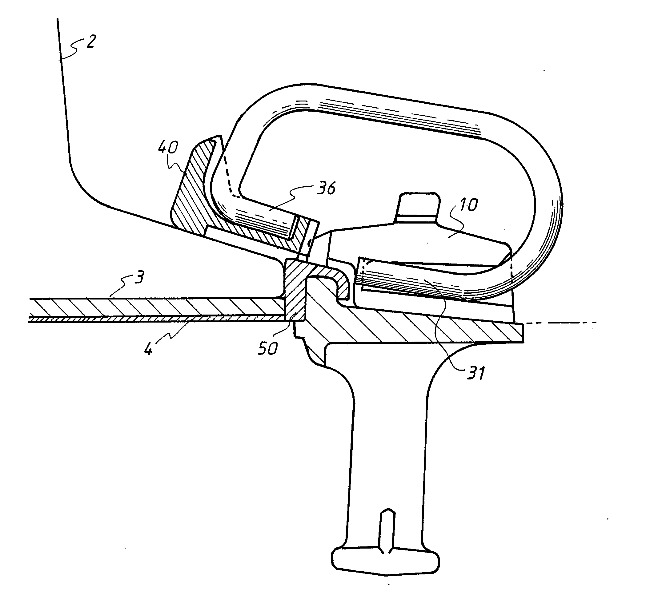
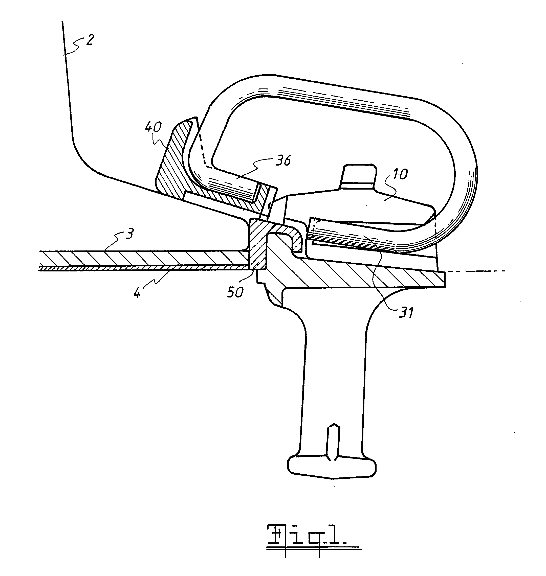
[0021]FIG. 1 is a detail of a side elevation illustrating one embodiment of this invention;

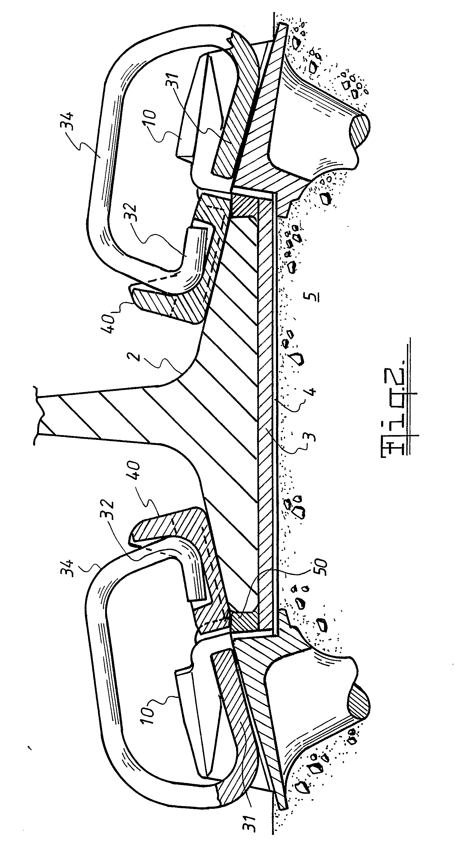
[0022]FIG. 2 is a side elevation of a typical rail seat of this invention showing a rail clip in the loaded position;

[0023]FIG. 3 is a side view of the assembly of FIG. 2 in a pre-loaded state;

[0024]FIG. 4 is a plan view of the second embodiment of the toe insulator of this invention;

[0025]FIG. 5 is a rear view of the second embodiment of the toe insulator shown in FIG. 4;

[0026]FIG. 6 is a front view of the second embodiment of the toe insulator shown in FIG. 4;

[0027]FIG. 7 is a side view of the second embodiment of the toe insulator shown in FIG. 4;

[0028]FIG. 8 illustrates the toe insulator of FIG. 4 during the loading of the clip into the shoulder;

[0029]FIG. 9 is a plan view of one of the shoulders of FIG. 3 in the preloaded state with the toe insulator of FIG. 4;

[0030]FIG. 10 is a side...


PUM


Abstract

A two-part rail clip insulator (40, 50) for a tie and rail seat assembly that enables the seat to be pre-assembled at the rail tie fabrication plant into a preloaded position where a rail (2) may be laid on the tie (5) on site, the clips (30) being movable to the loaded position after the rail is placed in position. The rail seat includes a concrete rail tie (5), a pair of rail clip support shoulders (10) cast in place in the tie (5), each shoulder (10) having a rail face between its external sides, a pair of shoulder insulators (50) each shaped to lie against the rail face of the rail shoulder, a pair of rail clips (30) each having a base section (31) adapted to seat within the support shoulder (10) and a toe section adapted to seat on the rail base; the arrangement being such that when the rail clip is in the preloaded position, the toe insulator (40) and the toe (36) of the clips do not project beyond the face of the shoulder insulator (50), so that a rail (2) can be laid between the rail shoulders and their associated insulators (50). The toe insulator (40) is shaped to facilitate loading of the rail clip (30) and resist movement of the clip or the rail during use.

Description

TECHNICAL FIELD[0001]This invention relates to a rail fastening assembly of the type where a rail is clamped to a rail seat by elastic rail fasteners held in shoulders fastened to the tie and insulators isolate the rail fastener and support shoulders from the rail. The present invention addresses problems associated with the insulators.BACKGROUND[0002]Concrete ties have been in use in some parts of the world for a long time but it is only since 1985 that they have been able to provide cost benefits for use in North America relative to wooden ties.[0003]One advantage of concrete ties is that the rail seats can be pre assembled with only a few components to be added on site when the rail is placed in position. The difficulty with this is that the pre assembled components can become dislodged during transport and some components still have to be positioned on the rail. The rail seats usually comprises a rail pad that is positioned below the rail, an abrasion resistant plate below the p...

Claims


Application Information

Patent Timeline
IPC IPC(8): E01B9/28E01B9/30
CPCE01B9/303
Inventor YOUNG, HARTLEY FRANKMEDIAVILLA, JOSE RICARDO
Owner PROGRESS RAIL SERVICES
Why Eureka
Try Eureka